How to make a push-button electronic regulator using one transistor. Goodbye variable resistor

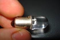
Using this electronic regulator, you can smoothly adjust the brightness of an LED strip or incandescent lamp, and regulate the speed of rotation of the electric motor shaft. Buttons are used for control; there are no variable resistors or microcircuits in the circuit.
You will need the following parts
- Transistor irfz44n.
- Resistor 4.7 MOhm.
- Resistor 82 kOhm - 2 pcs.
- Capacitor 0.68 µF.
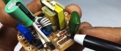
Manufacturing of the regulator
We take a field-effect transistor.

We secure it in the “third hand”. We solder a capacitor to the gate and source.

We solder an 82 kOhm resistor to the source.

Next are two buttons in sequence.

Then we connect the second button through an 82 kOhm resistor to the drain. And to the middle of the connection of the buttons we solder a 4.7 MOhm resistor and connect it to the gate.

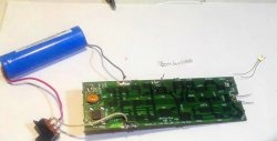
This “variable resistor” is connected to the open circuit of the load circuit.


To increase the brightness (or increase the engine speed), you need to press and hold the top button until the desired brightness appears.To reduce the brightness, you need to press the second button and hold it to the desired values. All changes occur very smoothly without any jerks.
Principle of operation
The operating principle of the regulator is very simple. Using the buttons, the capacitor is charged or discharged. Since it is connected in parallel to the gate of the transistor, it determines how open the field-effect transistor is.