How to make a drum sanding and calibrating machine for wood
To give an untreated board a perfectly smooth surface, sanding is required. If you do this with regular sandpaper or a hand sander, the surface will be smooth, but not even. You can simultaneously achieve the correct plane and remove roughness by constructing a grinding and calibrating machine. The proposed design of the machine repeats the operating principle of professional woodworking equipment, but the cost of its production is several times lower than its factory counterparts.

When producing a machine according to the proposed drawing, laths and beams of non-standard sizes are used, so cutting the wood will have to be done independently on a circular table with a stop. Timber with a thickness of more than 60 mm can be used as the raw material for cutting.
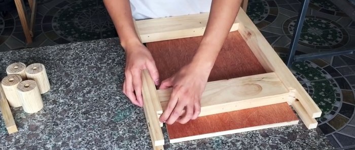
The first step is to make a conveyor table that will pass the workpieces under the grinding drum. This is a very important unit, so when assembling it, errors in the size of the drawing should be minimal. In two 55x36 mm bars, a cut is made using a milling cutter for further installation of the shaft. Milled bars with transverse slats and a plywood sheet are assembled into a table.
The same 15 mm plywood will be used as the base of the machine. A shield 570x740 mm is cut out of it. Along the longitudinal edges it is reinforced with two bars 30x80x740 mm.

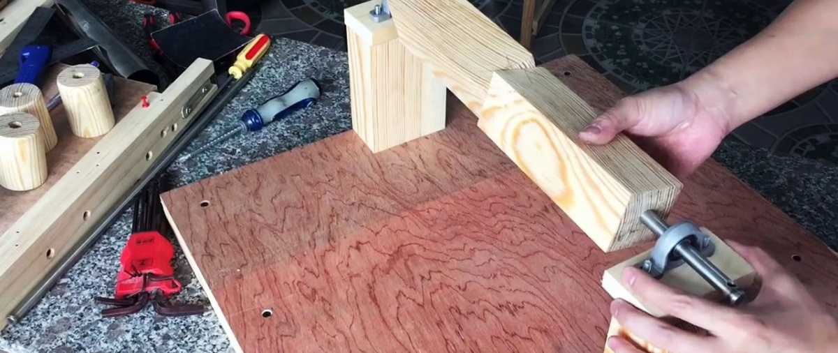
According to the drawing, 2 bars 95x55x147 mm are vertically fixed to the base. These will be used to install the sanding drum bearings.

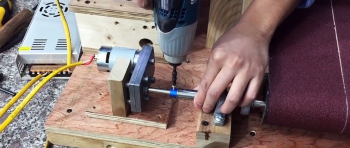
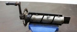
To make a grinding drum, take 2 bars, at the end of which a through hole is drilled for pressing in a 12 mm metal shaft. To join the bars tightly, nails without heads are inserted between them and glue is applied. When the bars are compacted, the nails will sink into both workpieces, preventing them from detaching due to friction and beating.

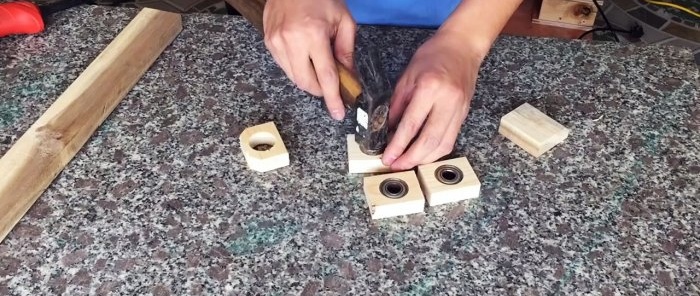
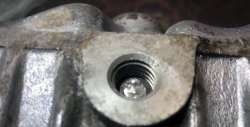
The resulting unpolished drum is attached to the support bars of the base of the machine. To do this, a substrate is made for each of them, into which a pair of M6 30 mm bolts are placed. Using bolts, flange support bearings are secured under the shaft. The drum blank is inserted into them.

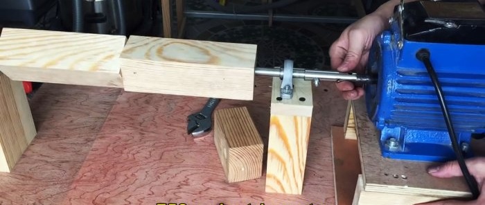
Next, according to the drawing, the engine stand is assembled.Its proposed dimensions are designed to fit the existing motor. If an engine of other dimensions is available, the height of the bars will need to be adjusted. The electric motor is connected to the drum shaft using a tube.
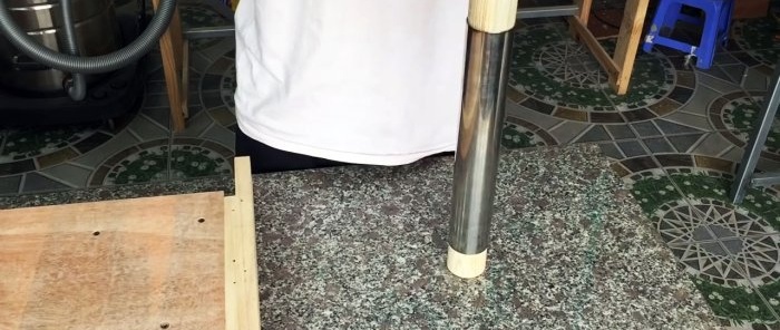
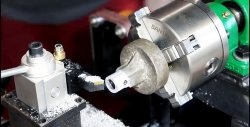
After starting the engine and making sure that it is operating without excessive vibration caused by distortions during assembly, you can give the shaft a cylindrical shape. To do this, you need to grind it down as evenly as possible. Ideally, this should be done on a lathe.

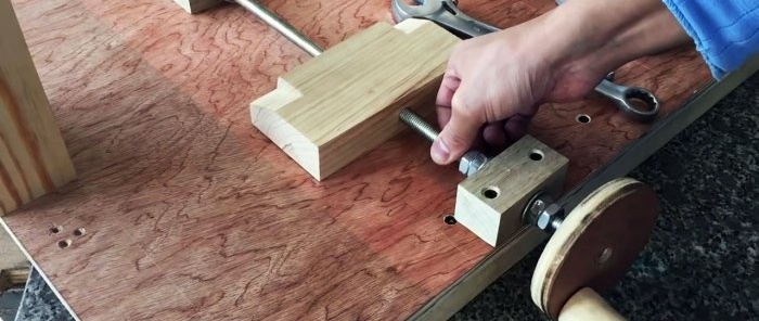
The next step is to assemble the gap adjustment mechanism between the conveyor table and the sanding drum. It is important to do everything exactly and according to the drawing. In order for everything to work like a clock, you need to tighten the locknuts well.
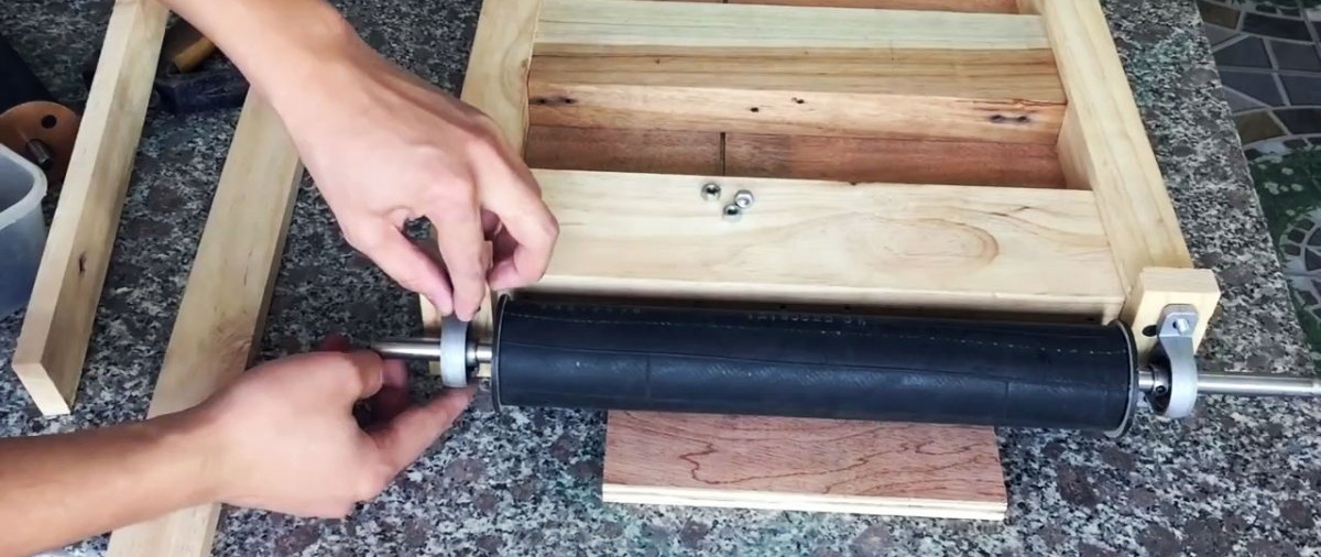
Next, 2 drums are made to move the conveyor belt. At their base, a d52 mm pipe is used. Wooden cylinders are pressed along its edges. In this case, a 12x475 mm shaft is placed in one drum, and a 10x355 mm shaft in the second. A bicycle tube is stretched over the top of the tubes.
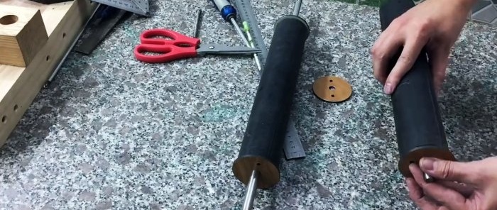
A long rubber-coated drum is fixed to the conveyor table using the same principle as a sanding drum.

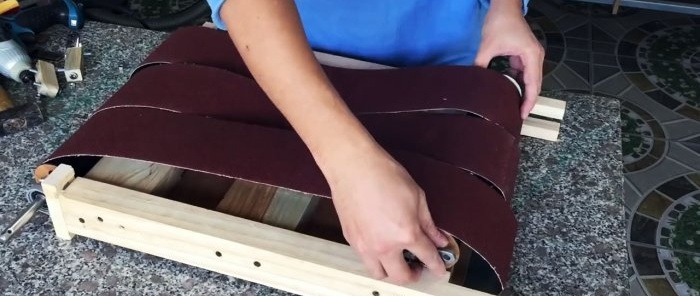
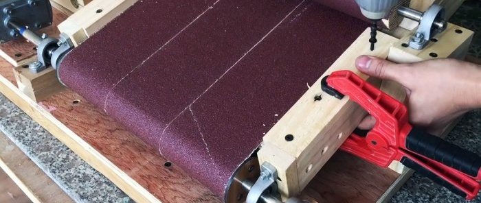
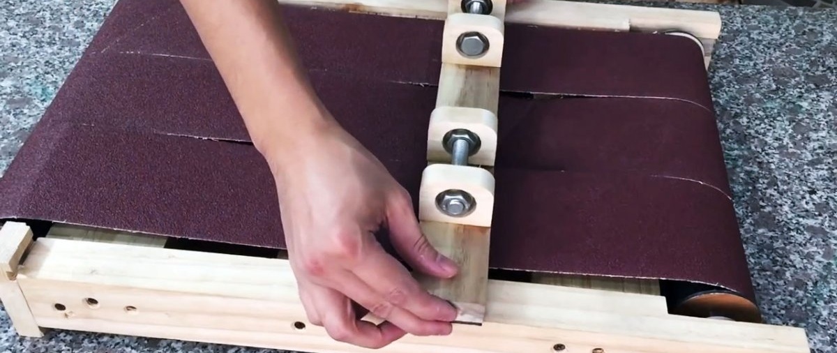
There are 3 sanding belts installed on the table, which need to be placed on a fixed rubberized drum. Next, a second drum with flanged bearings on the shafts is threaded under them. With their help, it will be screwed to the table on milled bars. To do this, you must first make inserts into the cutout from the router according to the drawing. Bolts are installed in them, to which the bearings are screwed. This will allow the tape to stretch.
Next, an adjusting support for the table is made. It is a rail with two rollers made of M12 90 mm bolts. To make them rotate, 4 bearings are used.The rail is attached to the back side of the conveyor table according to the drawing.

To fix the table to the base of the machine, 2 support bearings with flanges are used. The shaft of a long rubber-coated drum is inserted into them. The bearings themselves are screwed to the machine stand.
2 gussets are screwed to the previously made table tilt adjustment mechanism. Now, when the handle rotates, they move, thereby changing the gap between the grinding drum and the conveyor. In this case, the gussets do not rest against the tape, but against rollers made of M12 90 mm bolts.

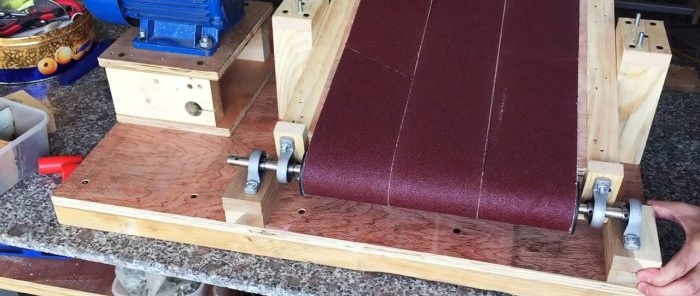
To make the conveyor belt move, you need to install a small motor with a reduction gear. It is connected to the same shaft, on which there are 4 support bearings with flanges.
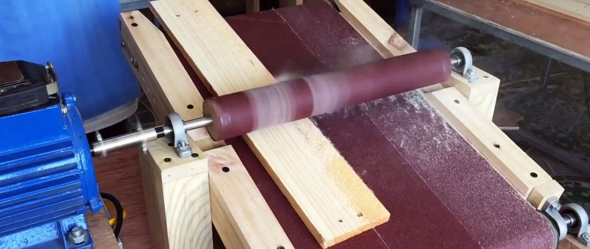
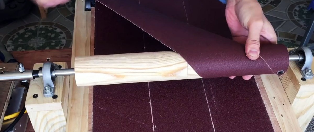
Sandpaper is wound onto the sanding drum. Limiters made of bars are screwed along the longitudinal edge of the table. In this form, the machine can already work.

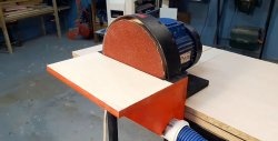
When the power is turned on for both motors, the drum and workpiece feeding belt begin to rotate. At the same time, the conveyor moves slowly. This makes it possible to achieve a fairly large material removal in one pass under the drum.
However, to combat flying wood dust, you also need to make a cover to connect the vacuum cleaner.

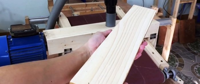
This project may take weeks to complete, but the result is an efficient, fully functioning machine. With its help, you can not only prepare the board, but also sand small furniture panels.
You can see detailed assembly, all dimensions and drawings in the video clip.
Basic materials:
- plywood 15 mm;
- any timber with a thickness of 60 mm;
- board 30x100 mm;
- shaft 12 mm;
- shaft 10 mm;
- 20 bolts M6 30 mm;
- 6 flange support bearings with an internal diameter of 12 mm;
- 4 bearings with an internal diameter of 12 mm;
- 2 flange bearings with an internal diameter of 10 mm;
- electric motor 750W;
- M12 pin;
- steel pipe d 52 mm;
- sanding belt 100x1200 mm;
- small 12V electric motor with reduction gear;
- 2 bolts M12 90 mm.
When producing a machine according to the proposed drawing, laths and beams of non-standard sizes are used, so cutting the wood will have to be done independently on a circular table with a stop. Timber with a thickness of more than 60 mm can be used as the raw material for cutting.
Manufacturing of the machine
The first step is to make a conveyor table that will pass the workpieces under the grinding drum. This is a very important unit, so when assembling it, errors in the size of the drawing should be minimal. In two 55x36 mm bars, a cut is made using a milling cutter for further installation of the shaft. Milled bars with transverse slats and a plywood sheet are assembled into a table.

The same 15 mm plywood will be used as the base of the machine. A shield 570x740 mm is cut out of it. Along the longitudinal edges it is reinforced with two bars 30x80x740 mm.

According to the drawing, 2 bars 95x55x147 mm are vertically fixed to the base. These will be used to install the sanding drum bearings.

To make a grinding drum, take 2 bars, at the end of which a through hole is drilled for pressing in a 12 mm metal shaft. To join the bars tightly, nails without heads are inserted between them and glue is applied. When the bars are compacted, the nails will sink into both workpieces, preventing them from detaching due to friction and beating.

The resulting unpolished drum is attached to the support bars of the base of the machine. To do this, a substrate is made for each of them, into which a pair of M6 30 mm bolts are placed. Using bolts, flange support bearings are secured under the shaft. The drum blank is inserted into them.
Next, according to the drawing, the engine stand is assembled.Its proposed dimensions are designed to fit the existing motor. If an engine of other dimensions is available, the height of the bars will need to be adjusted. The electric motor is connected to the drum shaft using a tube.

After starting the engine and making sure that it is operating without excessive vibration caused by distortions during assembly, you can give the shaft a cylindrical shape. To do this, you need to grind it down as evenly as possible. Ideally, this should be done on a lathe.

The next step is to assemble the gap adjustment mechanism between the conveyor table and the sanding drum. It is important to do everything exactly and according to the drawing. In order for everything to work like a clock, you need to tighten the locknuts well.

Next, 2 drums are made to move the conveyor belt. At their base, a d52 mm pipe is used. Wooden cylinders are pressed along its edges. In this case, a 12x475 mm shaft is placed in one drum, and a 10x355 mm shaft in the second. A bicycle tube is stretched over the top of the tubes.


A long rubber-coated drum is fixed to the conveyor table using the same principle as a sanding drum.
There are 3 sanding belts installed on the table, which need to be placed on a fixed rubberized drum. Next, a second drum with flanged bearings on the shafts is threaded under them. With their help, it will be screwed to the table on milled bars. To do this, you must first make inserts into the cutout from the router according to the drawing. Bolts are installed in them, to which the bearings are screwed. This will allow the tape to stretch.

Next, an adjusting support for the table is made. It is a rail with two rollers made of M12 90 mm bolts. To make them rotate, 4 bearings are used.The rail is attached to the back side of the conveyor table according to the drawing.

To fix the table to the base of the machine, 2 support bearings with flanges are used. The shaft of a long rubber-coated drum is inserted into them. The bearings themselves are screwed to the machine stand.

2 gussets are screwed to the previously made table tilt adjustment mechanism. Now, when the handle rotates, they move, thereby changing the gap between the grinding drum and the conveyor. In this case, the gussets do not rest against the tape, but against rollers made of M12 90 mm bolts.

To make the conveyor belt move, you need to install a small motor with a reduction gear. It is connected to the same shaft, on which there are 4 support bearings with flanges.

Sandpaper is wound onto the sanding drum. Limiters made of bars are screwed along the longitudinal edge of the table. In this form, the machine can already work.

When the power is turned on for both motors, the drum and workpiece feeding belt begin to rotate. At the same time, the conveyor moves slowly. This makes it possible to achieve a fairly large material removal in one pass under the drum.
However, to combat flying wood dust, you also need to make a cover to connect the vacuum cleaner.

This project may take weeks to complete, but the result is an efficient, fully functioning machine. With its help, you can not only prepare the board, but also sand small furniture panels.

Watch the video
You can see detailed assembly, all dimensions and drawings in the video clip.
Similar master classes


Particularly interesting


Comments (0)
