How to make a charger for car batteries from available parts
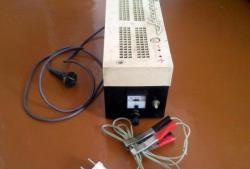
Now we have to stay at home. Boring. The housing with the power transformer became free. While wondering what to do with it, I decided to do a long-standing project. Although I have a similar device, I will make more. I will make a charger for lead batteries. This is a “from what is available” option.
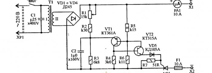
The scheme I will use to assemble it is simple. This is a regular switching regulator. Details available.
About the components:
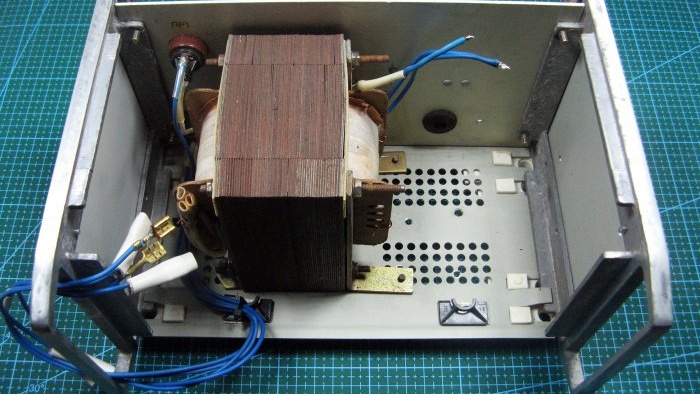
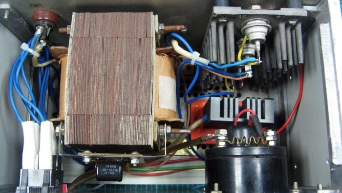
I have the housing with the transformer from an old project. Transformer for 17-18 volts. Do not need anymore.
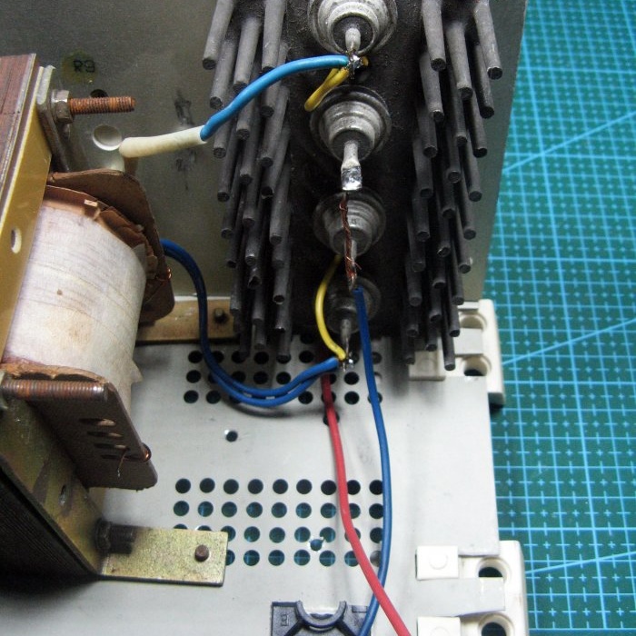
The diode bridge was ready, assembled from 4 D242B diodes. Diodes are installed through the insulation. Can be attached directly to the body.
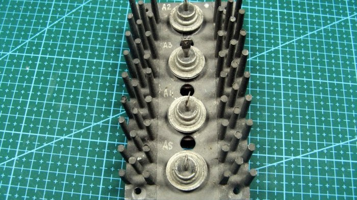
Thyristor KU202E. I installed it on a radiator, I didn’t count the area, but it shouldn’t get too hot. You can install any of this series.

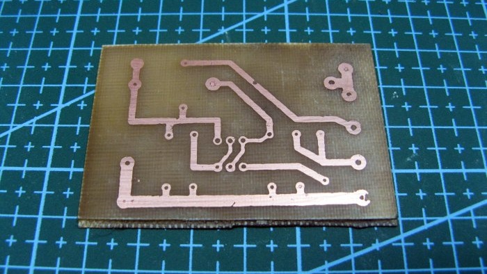
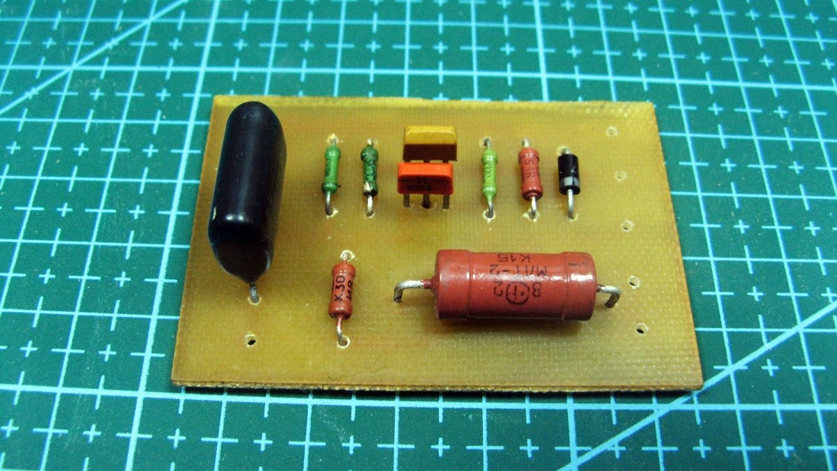
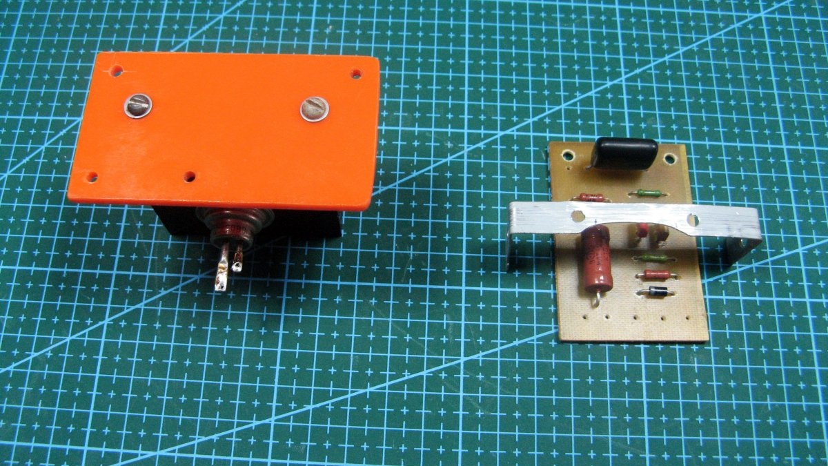
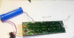
The board was made using the LUT method. Some places are a little over-etched, I'll correct them with solder. I am attaching the board in lay6 format.
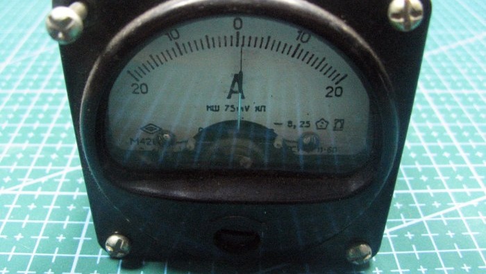
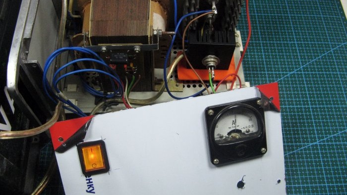
Ammeter 20 Amp.It was bipolar, there is not much difference. I need to install “O”, it’s a little upset for me.
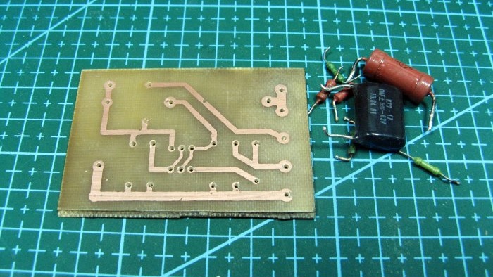
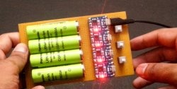
I drilled holes on the board. Drilled with a diameter of 1.2 mm. I picked up the radio components, not all of them are in the photo. Everything is on the list. Any 0.125 W resistors will do, it’s been tested and they don’t get hot. R5 at 2 watts.
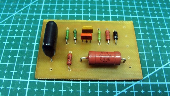
I install radio components and solder them. Transistors with the letter E. I installed them last.
I'm installing a diode bridge. I screw it through the racks to the rear wall of the case.
I screwed the radiator with the thyristor to a piece of plastic. Now he is isolated. I'll screw the plate through the racks in the case. I will mount the board on the transformer pin. For fastening, I cut out a bracket. I made a cut in the bracket for the capacitor.

I marked the front panel and cut out holes for the controls.
My adjusting resistor is 25 kOhm.

I unsoldered everything and screwed on the front panel.
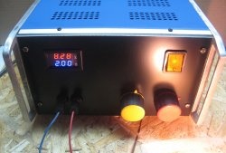
I connected the battery and checked the current regulation. It produces 15 amperes for a short time, my thyristor is 10 amperes. So let's not overdo it.
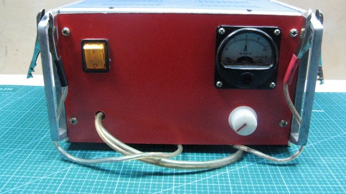
This is the charger we got. As it charges, the current drops. The battery is charged when the current is zero.

Scheme
The scheme I will use to assemble it is simple. This is a regular switching regulator. Details available.

Accessories
- - details according to the diagram;
- - Ammeter;
- - diode bridge;
- - thyristor;
- - frame;
- - transformer;
- - tools.
About the components:
I have the housing with the transformer from an old project. Transformer for 17-18 volts. Do not need anymore.

The diode bridge was ready, assembled from 4 D242B diodes. Diodes are installed through the insulation. Can be attached directly to the body.

Thyristor KU202E. I installed it on a radiator, I didn’t count the area, but it shouldn’t get too hot. You can install any of this series.

The board was made using the LUT method. Some places are a little over-etched, I'll correct them with solder. I am attaching the board in lay6 format.
zu-na-tiristore.zip
[3.12 Kb] (downloads: 2842)

Ammeter 20 Amp.It was bipolar, there is not much difference. I need to install “O”, it’s a little upset for me.

Assembly
I drilled holes on the board. Drilled with a diameter of 1.2 mm. I picked up the radio components, not all of them are in the photo. Everything is on the list. Any 0.125 W resistors will do, it’s been tested and they don’t get hot. R5 at 2 watts.

I install radio components and solder them. Transistors with the letter E. I installed them last.
I'm installing a diode bridge. I screw it through the racks to the rear wall of the case.

I screwed the radiator with the thyristor to a piece of plastic. Now he is isolated. I'll screw the plate through the racks in the case. I will mount the board on the transformer pin. For fastening, I cut out a bracket. I made a cut in the bracket for the capacitor.
I marked the front panel and cut out holes for the controls.
My adjusting resistor is 25 kOhm.

I unsoldered everything and screwed on the front panel.

I connected the battery and checked the current regulation. It produces 15 amperes for a short time, my thyristor is 10 amperes. So let's not overdo it.

This is the charger we got. As it charges, the current drops. The battery is charged when the current is zero.
Watch the video
Similar master classes

Particularly interesting

Comments (11)
