How to convert a computer power supply into a charger

There was a need to charge the car battery. You can take LBP, but I use it in the workshop. I decided to build a charger for the garage.
I'm thinking about an idea
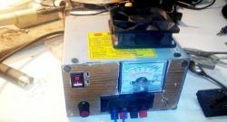
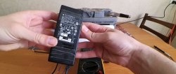
Thinking through the design, I decided to focus on reworking the computer's power supply. Having studied information from the Internet, the task is quite simple. I found a power supply in stock at an interesting microcircuit 2003. It combines PWM and control of the deviation of the main output voltages of the unit. This is the model block. There are probably others, but this is the one I have.
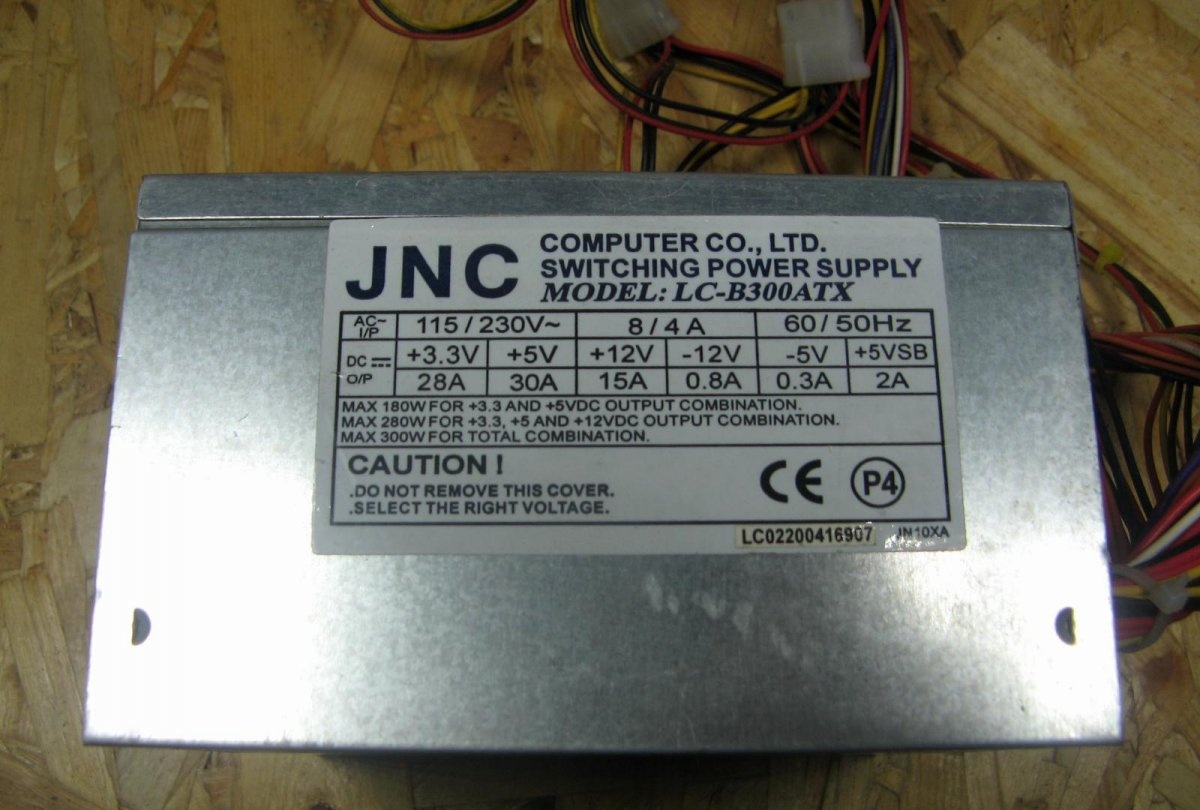
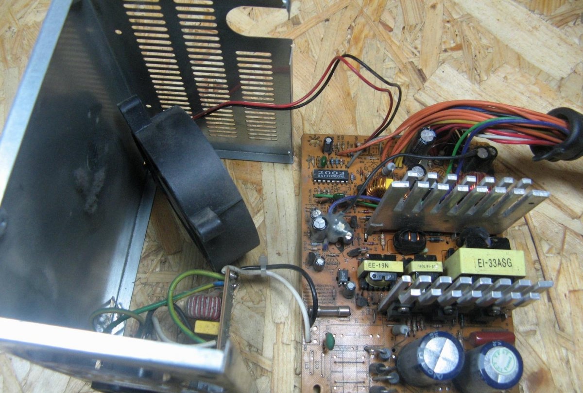
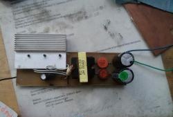
I open it and clean it from dust. The power supply must be working.
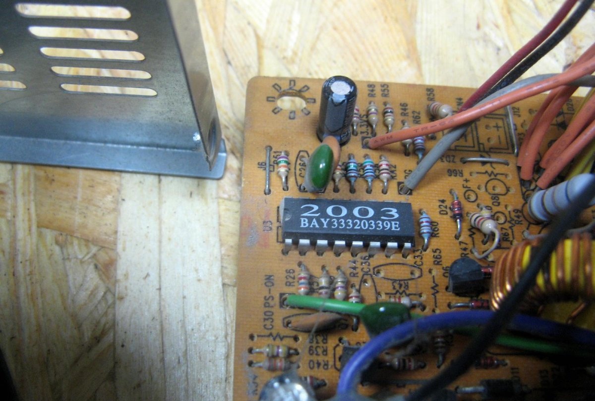
Here's a close-up of the chip. There is very little information about her. The search focused on the diagram of the power supply itself and everything is practically clear.
Computer block diagram
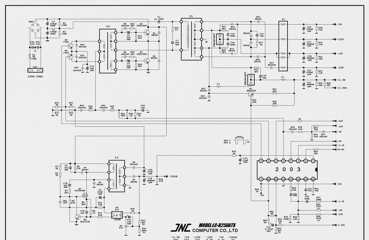
The diagram has this initial appearance. Although the diagram indicates 300 watts, my unit is assembled in the same way, the difference is apparently in some components.
Converting the block into a charger with your own hands
Items marked in red need to be removed. The yellow resistor is changed to 2.4 kOhm. Marked in blue, you need to replace it with a trimming resistor.I also unsoldered the radiator with diodes, without it it is convenient to look for components to remove. Voltages marked in green will be soldered to the error bypass board.

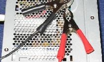
The photo clearly shows the removed details. I also removed capacitor C27 and resistor R53 for now. I'll solder the resistor back later, it's needed for uninterrupted charging. PS-ON was soldered to minus with a wire to start the unit.

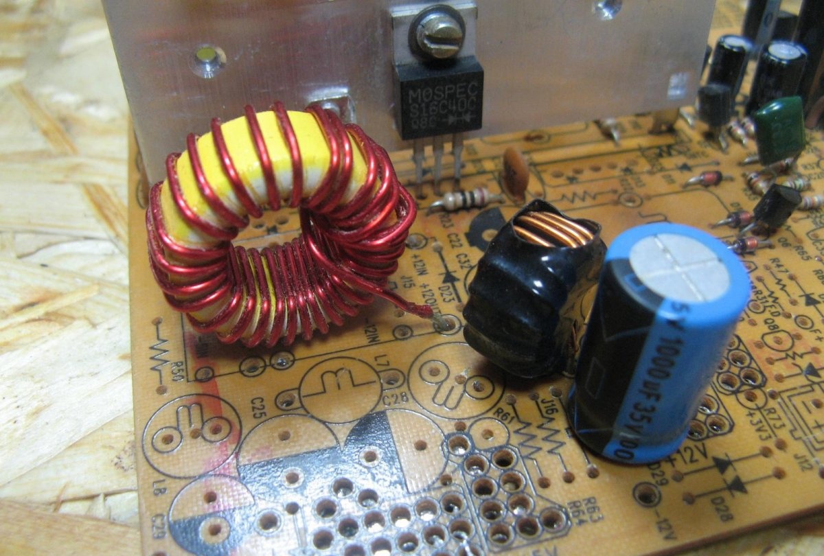
I installed an additional choke on the 12 volt line and removed it from the 5 volt line. A dual diode was used from the 5 volt line.
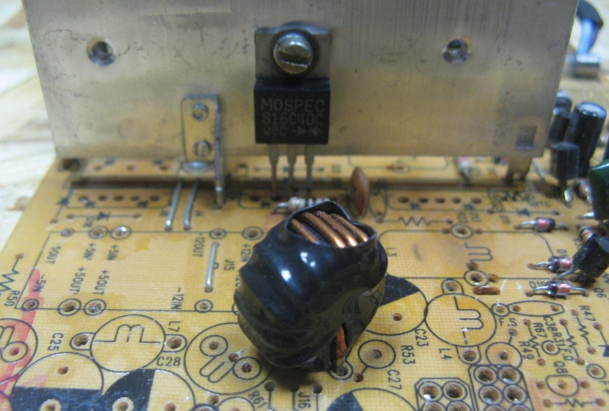
The group stabilization choke freed from unnecessary windings. The wire cross-section is sufficient for my purposes.
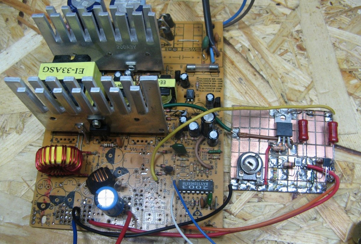
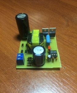
To bypass the main voltage deviation control, I made a separate board. I made the board on a similar breadboard. The board will be powered by 17 volts from the duty room. I will lower the voltage using LM317, a 12 volt stabilizer has been assembled. The stabilizers on the TL431 will be powered from 12 volts. I assembled two stabilizers, 5 and 3.3 volts. The missing resistor in the middle circuit is 130 ohms.

This is how the board turned out. I assembled it in half an hour.

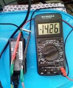
I solder the wires according to our diagram. The blue and white wires are the wires from the trimming resistor. When turned on, I set the output to 14.3 volts.
I measure the resistance of the resistor and it turns out to be about 12 kOhm. I solder in a combined resistor of two.

The output wires were taken from the first ones available, and just soldered “crocodiles” to them.

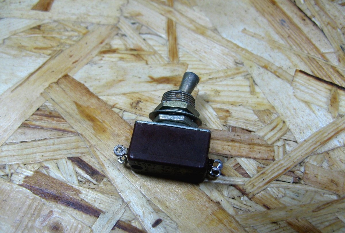
I disconnect the network cable with a Soviet TV2-1 switch.
I screw the power supply board onto the standard holes. I screwed the “fake” board to the radiator. I installed a dual diode at the output, a simple protection against polarity reversal. You need to be careful, there is no short circuit protection, I'll assemble it later. I solder the output wires. The fan was connected to the fake board, 12 volts. Indicator Light-emitting diode soldered to the charging output.

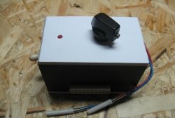
Forgot to mention. While I was finalizing the power supply board, the case in which the board was originally lost got lost. I picked up a similar box. Luckily I have plenty of them.

Light-emitting diode secured with hot glue.

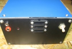
The front panel is made of plexiglass. I screw the toggle switch to the panel, take out the output wires and install Light-emitting diode. The panel was secured with screws. We put it on and screw the lid on.
Bottom line
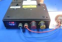
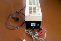
This is the charger I got. Just what you need for the garage. If you do not discharge the battery to the limit, the current is approximately 5 Amps. As it charges, the current drops.
Watch detailed video
Similar master classes
Particularly interesting
Comments (10)
