How to turn a bolt into a combination lock
Some crafts are interesting not only for their purpose, but also for their original technical design. These, of course, include a combination lock.

Its manufacture requires time, considerable effort, extreme care and the following materials:

Equipment we can't do without:
The work consists of three stages: production of parts and assemblies, assembly and installation of a code combination of numbers.
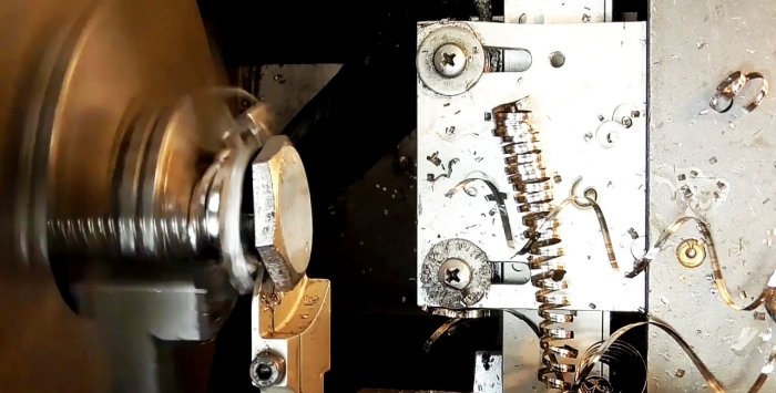
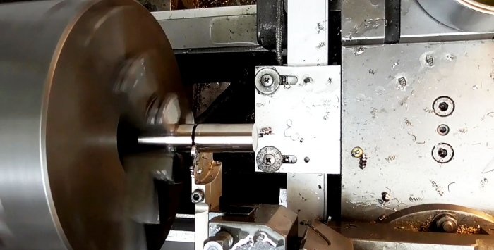
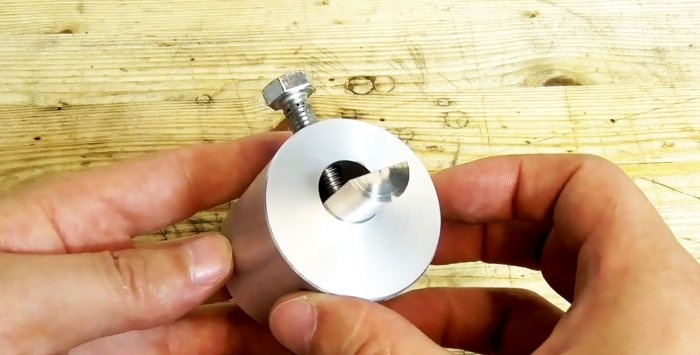
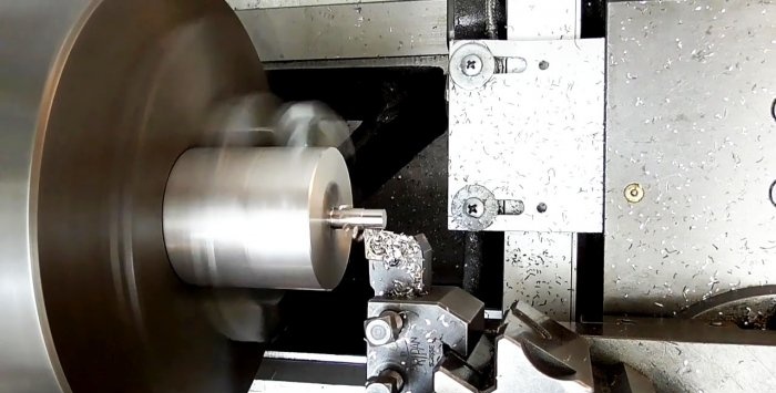
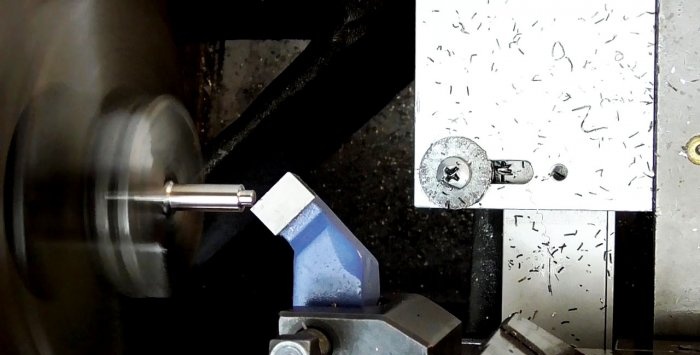
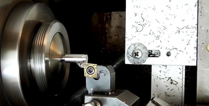
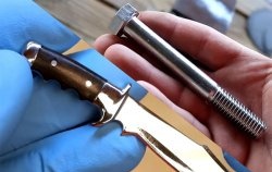
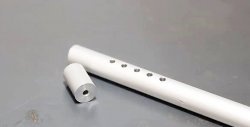
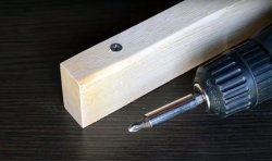
On a lathe, we divide the bolt head into two halves, and grind the rod to the depth of the thread profile.
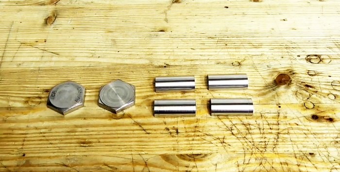
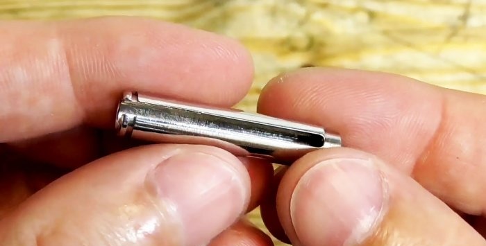
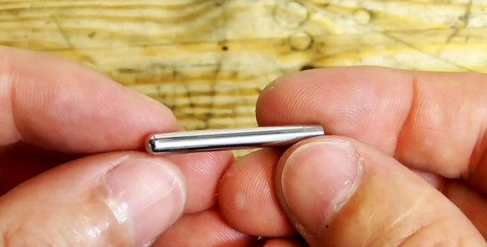
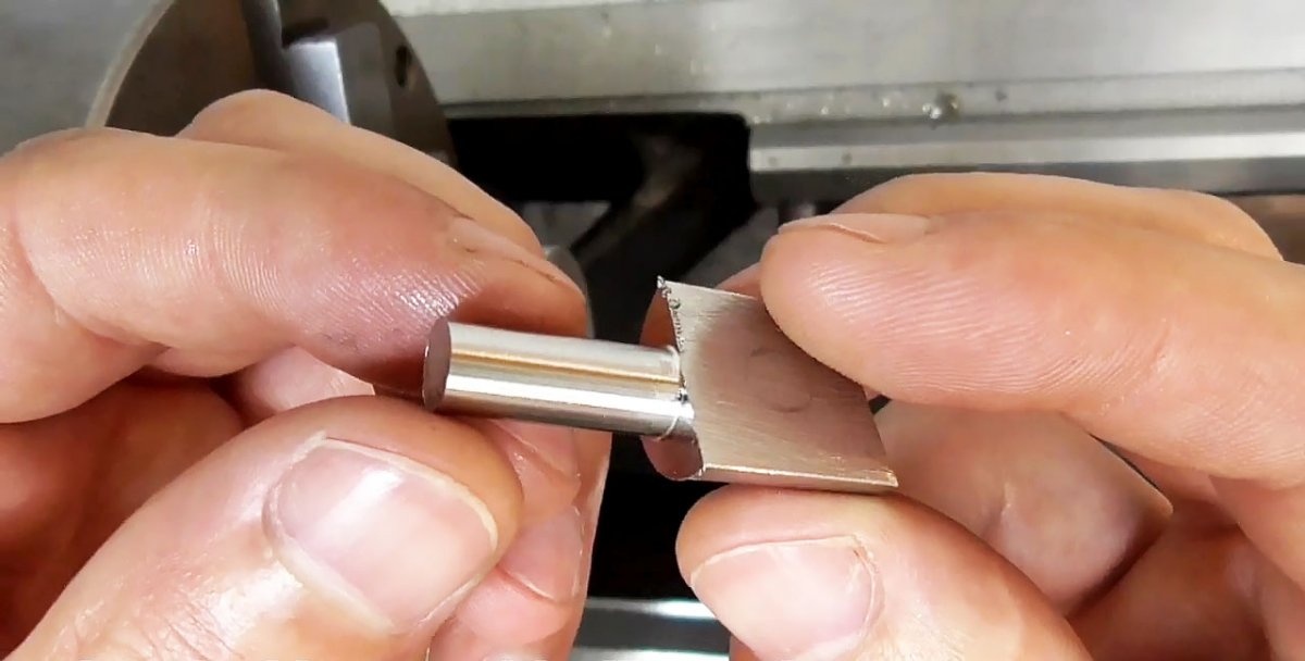
We clamp one part of the rod in a vice and saw it with a metal saw into two longitudinal halves.

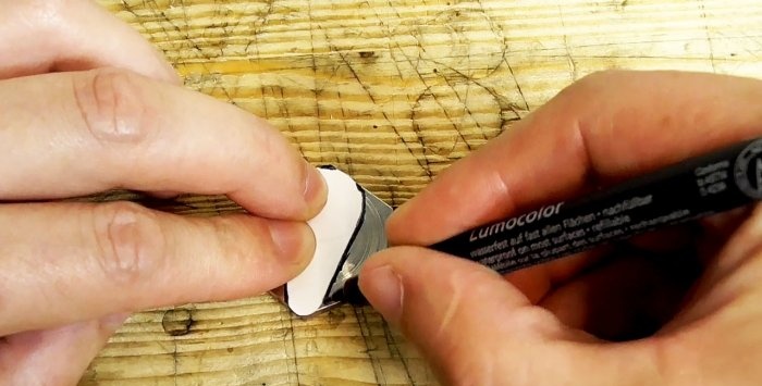
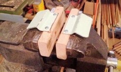
On one of the hexagonal plates, using a template and a marker, draw the outline of the side lining of the lock.
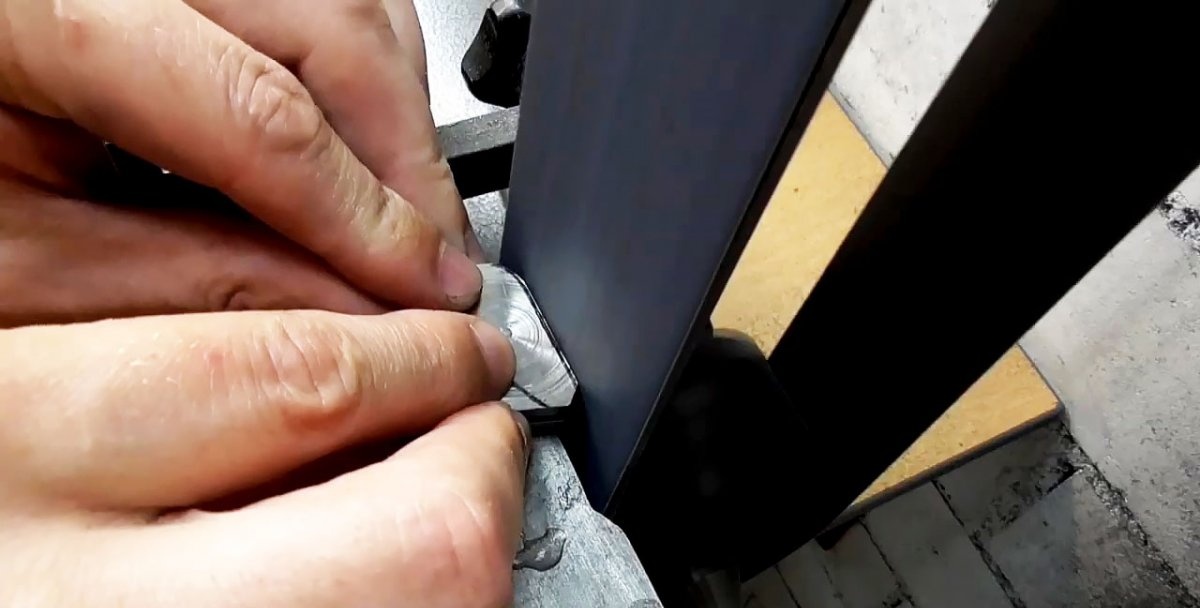
We grind the glued hexagons on a grinder along the marked contour of the side lining of the lock and drill holes at the ends.


We insert into the holes the “legs” of round templates, which are used only to draw the outline of the side pads of the lock on the grinder.

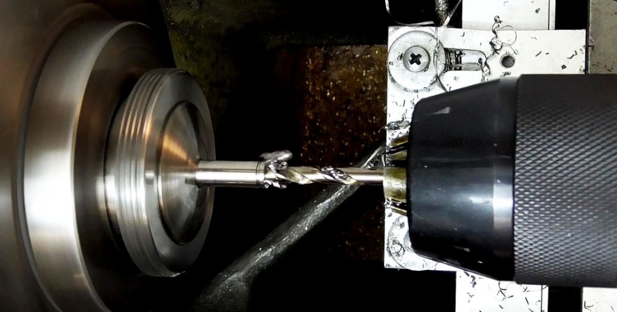
On a drilling machine, using a drill and an end mill, we form the finishing profile of the holes in the side plates. Around the large hole, we make 9 indentations evenly in a circle using an end mill.

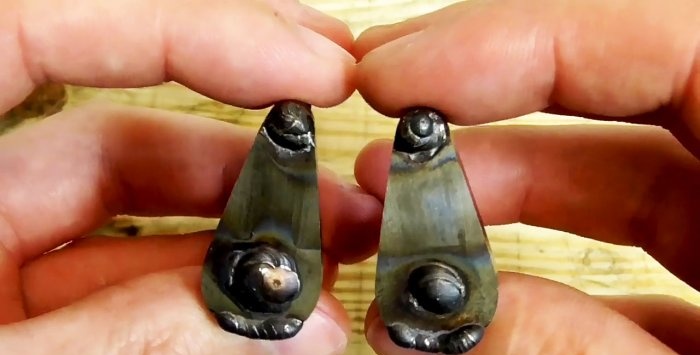
Using a soft wheel, polish all surfaces of the side linings of the lock.


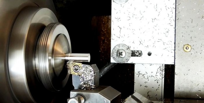
From 4 half-cylinders, using a special clamp, we sharpen a round rod on a lathe to the middle of the workpiece.


The first pin is for the wheels on the mounting side. It has a seat for a hole on one side, and an annular groove for a retaining ring and a blind hole on the other.

Using a milling cutter, we make a longitudinal groove in it for the entire length of the blind hole.


The second pin from the fastening side looks like a solid round rod with a seat for a hole in the side plate of the lock and a blind longitudinal drilling.


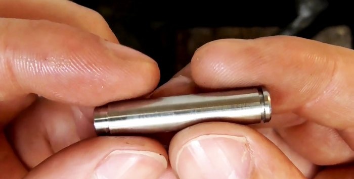
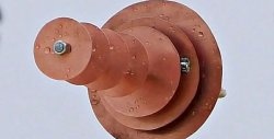
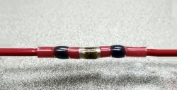
The third key pin on the moving side is also machined under the solid cylinder. Then one side is clamped into a cartridge with a gasket to shift the axis of the roller away from the axis of rotation of the cartridge. As a result, when processed with a cutter, a round tenon of smaller diameter is formed, the center of which does not coincide with the center of the pin.


Then, by milling, we form two shelves on both sides of the offset tenon. The result is a rod with two faces connected by circular arcs.

Using the same cutter, we reduce the cross-section of the rod on the larger side using symmetrical processing.
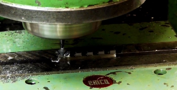

Using an end mill we make 5 rectangular and equal grooves. As a result, 5 equal protrusions are also formed.
Using files, needle files and sandpaper, the rod with all the protrusions is given the desired shape and the edges and ribs are rounded. Finally, polish this and all other rods with a soft wheel.


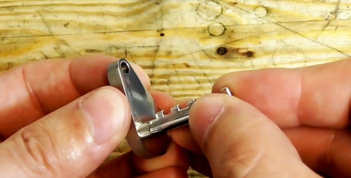
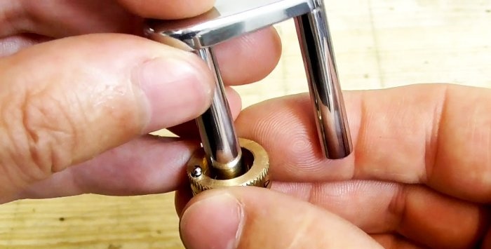
We insert the rod into its place in the side plate of the lock.
The fourth pin, which performs the function of the upper shaft on the movable side, is machined to the size of the hole in the side plate of the lock and, on one side, is shaped into a hemisphere using a file and a soft circle. We also insert it into place.

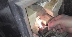
We weld all the pins on the back side to the side plates of the lock.
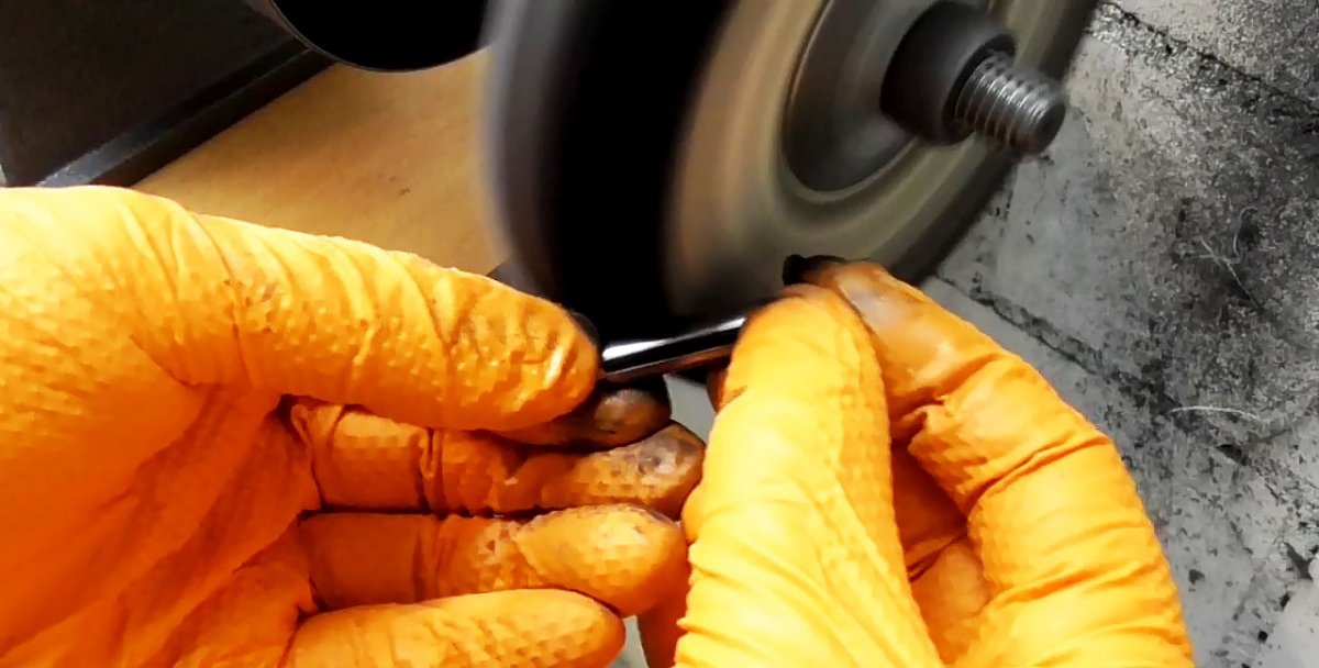
We grind and polish the welds on a grinder, round the edges with a file, finish with sandpaper and polish with a soft wheel.

Using a set of files, we form a groove at the end of the pin with a longitudinal slot. We try on the insertion of the movable pins into the holes of the fixed ones.


We make 4 brass wheels with numbers. After cutting them to size, we cut their blanks on a lathe, first drilling a through hole in the center and expanding it, on the one hand, to a certain depth.


The fifth wheel differs from others by the presence of a central groove on both sides, one of which is deeper than the other.
Columns of numbers for application on the forming wheels are printed on silicone-coated paper in a mirror image.
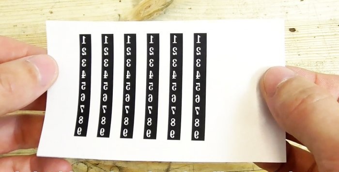
We cut out vertical strips of numbers with scissors and glue them onto the forming wheels.

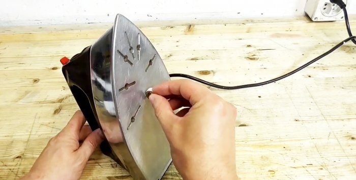
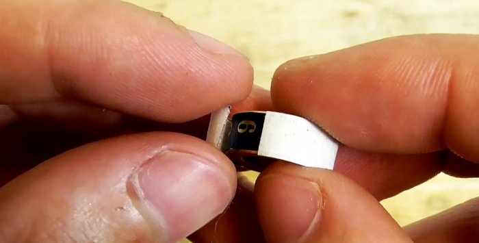
We transfer the numbers to the surface of the forming wheels, rolling them along the sole of a hot iron. As a result, the paper separates, and a layer of silicone with numbers sticks to the ring.
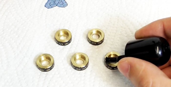
To protect all surfaces of the wheels, except those with numbers, we cover them with nail polish.
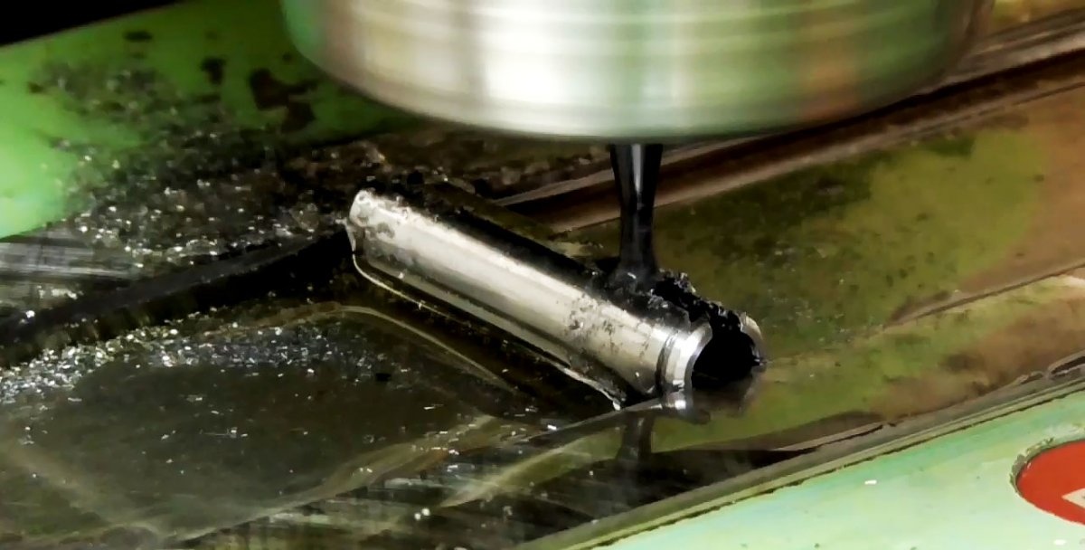
We string the wheels onto a wire, place them at the bottom of an inclined ditch and fill them with ferric chloride solution for etching for 45 minutes, which makes the wheels attractive and the numbers contrasting.

Next, we string the wheels onto a special mandrel, tighten them with a nut and clamp them in the lathe chuck. Next, we process the wheel block with sandpaper and polish it with a nap cloth.
We clamp the wheels into a special holder and use a milling machine to make a semicircular groove with a cutter until it exits into a large hole.
At the ends of the wheels we make 9 indentations evenly in a circle.


We fix the wheels one by one on the mandrel and clamp them in the chuck of the lathe. We bring the adjusted knurling to the wheel, lubricate them with oil and turn on the machine. A circular notch is rolled on the wheel at the end with a narrow strip.

Use a cutter to remove burrs from the end of the notch.
We drill 0.8 mm blind holes with a drill at the ends of the wheels with a notch opposite the semicircular groove.

Again, we put the wheels on the mandrel one by one and apply black paint to the digital recesses, removing the excess with a flat surface, pressing it against the rotating wheel, and then with a soft cloth.


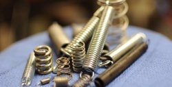
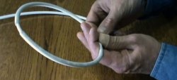
Using a special mandrel for winding springs, mounted on a lathe, we make 5 similar springs from 0.3 mm spring steel wire.

To hold the wire on the mandrel when winding the springs, we use pliers, and to cut off the ends, we use metal scissors.
To assemble wheels with numbers, in addition to springs, we will need 5 steel balls of 2 mm.

We insert a spring into the blind holes in the wheels and cover it with a ball on top.
Then we string all 5 wheels with springs and balls onto the upper shaft.
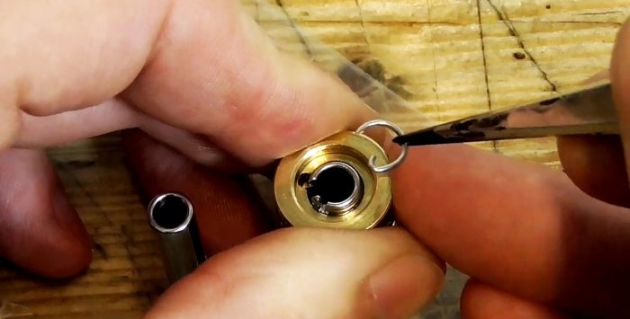
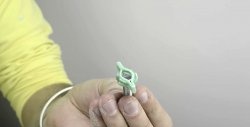
Using 0.8 mm spring steel wire on a simple mandrel, clamped in a vice, using pliers and wire cutters, we make a stop-lock for squeezing and holding the wheels with numbers on the rod.

We insert one end of the stopper into the groove at the end of the rod with tweezers, press the stopper in the middle, then the second edge securely covers and holds everything that is under it.


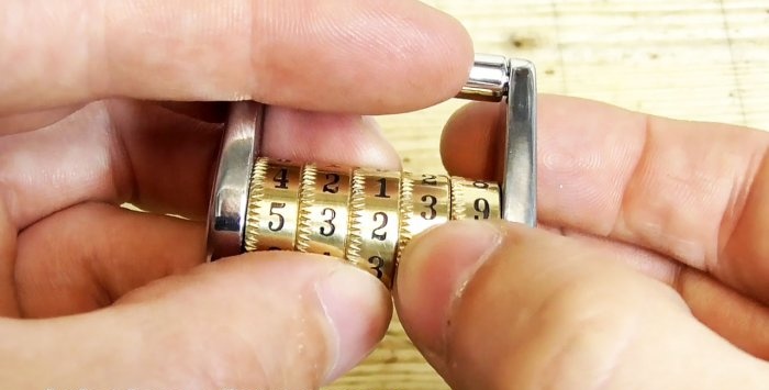
All that remains is to insert the second side of the combination lock with the rods into place and the device is ready for use. But for now the lock is locked, because a random combination of numbers has been set. The code set of numbers is determined by the location of the locking elements on the wheels and is exclusive for each lock.


Will need
Its manufacture requires time, considerable effort, extreme care and the following materials:

- stainless steel bolt M20 × 70;
- knurling wheel;
- means for applying numbers to wheels;
- steel balls;
- spring steel wire (0.3 and 0.8 mm).
Equipment we can't do without:
- lathe, drilling and milling machine;
- bench vice;
- pliers;
- hacksaws for metal;
- grinder;
- scissors for metal and paper cutting;
- mandrels for winding springs and retaining rings.
Manufacturing technology
The work consists of three stages: production of parts and assemblies, assembly and installation of a code combination of numbers.
Manufacturing of parts and assemblies
Side lock pads
On a lathe, we divide the bolt head into two halves, and grind the rod to the depth of the thread profile.


We clamp one part of the rod in a vice and saw it with a metal saw into two longitudinal halves.


On one of the hexagonal plates, using a template and a marker, draw the outline of the side lining of the lock.

We grind the glued hexagons on a grinder along the marked contour of the side lining of the lock and drill holes at the ends.

We insert into the holes the “legs” of round templates, which are used only to draw the outline of the side pads of the lock on the grinder.

On a drilling machine, using a drill and an end mill, we form the finishing profile of the holes in the side plates. Around the large hole, we make 9 indentations evenly in a circle using an end mill.

Using a soft wheel, polish all surfaces of the side linings of the lock.


Pins
From 4 half-cylinders, using a special clamp, we sharpen a round rod on a lathe to the middle of the workpiece.


The first pin is for the wheels on the mounting side. It has a seat for a hole on one side, and an annular groove for a retaining ring and a blind hole on the other.

Using a milling cutter, we make a longitudinal groove in it for the entire length of the blind hole.

The second pin from the fastening side looks like a solid round rod with a seat for a hole in the side plate of the lock and a blind longitudinal drilling.


The third key pin on the moving side is also machined under the solid cylinder. Then one side is clamped into a cartridge with a gasket to shift the axis of the roller away from the axis of rotation of the cartridge. As a result, when processed with a cutter, a round tenon of smaller diameter is formed, the center of which does not coincide with the center of the pin.


Then, by milling, we form two shelves on both sides of the offset tenon. The result is a rod with two faces connected by circular arcs.

Using the same cutter, we reduce the cross-section of the rod on the larger side using symmetrical processing.


Using an end mill we make 5 rectangular and equal grooves. As a result, 5 equal protrusions are also formed.
Using files, needle files and sandpaper, the rod with all the protrusions is given the desired shape and the edges and ribs are rounded. Finally, polish this and all other rods with a soft wheel.


We insert the rod into its place in the side plate of the lock.
The fourth pin, which performs the function of the upper shaft on the movable side, is machined to the size of the hole in the side plate of the lock and, on one side, is shaped into a hemisphere using a file and a soft circle. We also insert it into place.


Welding, grinding, polishing
We weld all the pins on the back side to the side plates of the lock.

We grind and polish the welds on a grinder, round the edges with a file, finish with sandpaper and polish with a soft wheel.

Using a set of files, we form a groove at the end of the pin with a longitudinal slot. We try on the insertion of the movable pins into the holes of the fixed ones.


Brass wheels with numbers
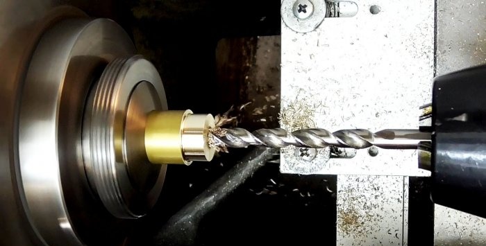
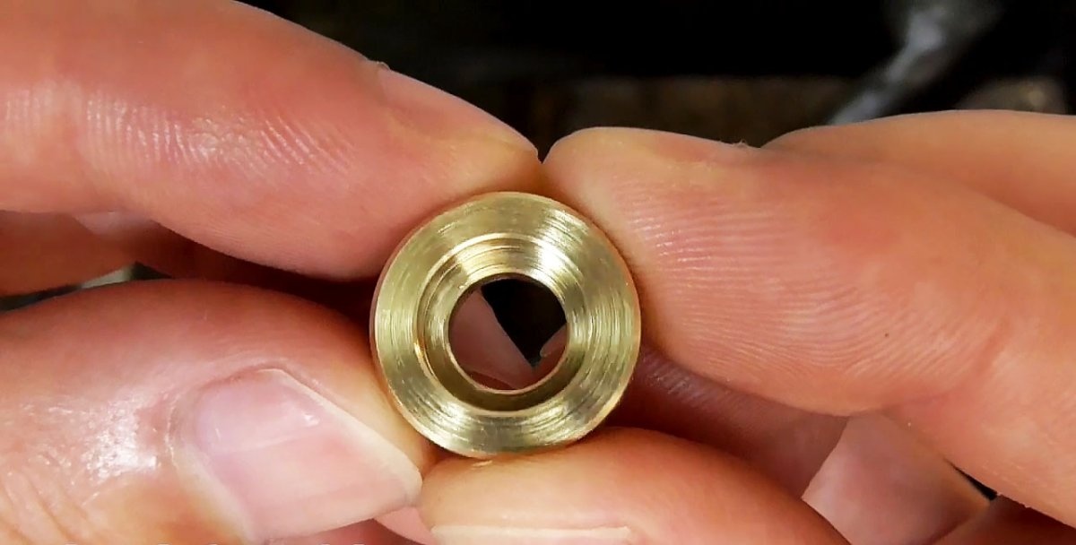
We make 4 brass wheels with numbers. After cutting them to size, we cut their blanks on a lathe, first drilling a through hole in the center and expanding it, on the one hand, to a certain depth.


The fifth wheel differs from others by the presence of a central groove on both sides, one of which is deeper than the other.
Columns of numbers for application on the forming wheels are printed on silicone-coated paper in a mirror image.

We cut out vertical strips of numbers with scissors and glue them onto the forming wheels.

We transfer the numbers to the surface of the forming wheels, rolling them along the sole of a hot iron. As a result, the paper separates, and a layer of silicone with numbers sticks to the ring.


To protect all surfaces of the wheels, except those with numbers, we cover them with nail polish.

We string the wheels onto a wire, place them at the bottom of an inclined ditch and fill them with ferric chloride solution for etching for 45 minutes, which makes the wheels attractive and the numbers contrasting.


Next, we string the wheels onto a special mandrel, tighten them with a nut and clamp them in the lathe chuck. Next, we process the wheel block with sandpaper and polish it with a nap cloth.
We clamp the wheels into a special holder and use a milling machine to make a semicircular groove with a cutter until it exits into a large hole.
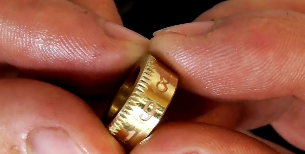
At the ends of the wheels we make 9 indentations evenly in a circle.


We fix the wheels one by one on the mandrel and clamp them in the chuck of the lathe. We bring the adjusted knurling to the wheel, lubricate them with oil and turn on the machine. A circular notch is rolled on the wheel at the end with a narrow strip.
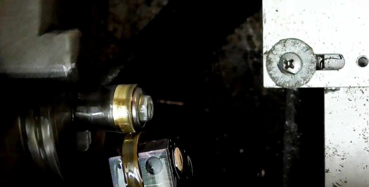
Use a cutter to remove burrs from the end of the notch.
We drill 0.8 mm blind holes with a drill at the ends of the wheels with a notch opposite the semicircular groove.

Again, we put the wheels on the mandrel one by one and apply black paint to the digital recesses, removing the excess with a flat surface, pressing it against the rotating wheel, and then with a soft cloth.


Additional parts, assembly and coding
Using a special mandrel for winding springs, mounted on a lathe, we make 5 similar springs from 0.3 mm spring steel wire.


To hold the wire on the mandrel when winding the springs, we use pliers, and to cut off the ends, we use metal scissors.
To assemble wheels with numbers, in addition to springs, we will need 5 steel balls of 2 mm.

We insert a spring into the blind holes in the wheels and cover it with a ball on top.


Then we string all 5 wheels with springs and balls onto the upper shaft.
Using 0.8 mm spring steel wire on a simple mandrel, clamped in a vice, using pliers and wire cutters, we make a stop-lock for squeezing and holding the wheels with numbers on the rod.

We insert one end of the stopper into the groove at the end of the rod with tweezers, press the stopper in the middle, then the second edge securely covers and holds everything that is under it.


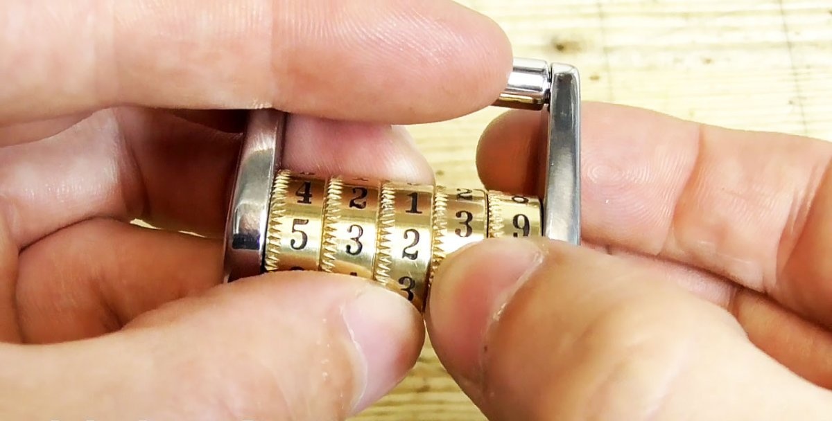
All that remains is to insert the second side of the combination lock with the rods into place and the device is ready for use. But for now the lock is locked, because a random combination of numbers has been set. The code set of numbers is determined by the location of the locking elements on the wheels and is exclusive for each lock.

Watch the video
Similar master classes
Particularly interesting
Comments (2)
