How to make a balancing unit using transistors for any number of lithium-ion batteries

Lithium-ion batteries are extremely sensitive to overcharging. And as soon as you recharge the battery a little, it immediately breaks down. To ensure that batteries are charged evenly in a series circuit, balance protection circuits are used to prevent overcharging.
It is not difficult to assemble such a controller yourself using transistors.
Will need
To manufacture one balancing controller cell, the following parts will be required:- Stabilizer TL431 - http://alii.pub/5mclsi
- Transistor BD140 - http://alii.pub/5p9tso
- 4 diodes 1N4007 - http://alii.pub/5m5na6
- Light-emitting diode - http://alii.pub/5lag4f
- Resistors 330 Ohm, 1 kOhm, 20 kOhm - 2 pcs. - http://alii.pub/5h6ouv
- Variable resistor 20 kOhm - http://alii.pub/5o27v2
Diagram and operation of the BMS controller using the example of one cell

The circuit is connected in parallel to the battery and monitors the voltage on it. When a voltage above 4.2 V is reached during charging, further increases are blocked.
It is based on an adjustable stabilizer chip TL431. Which controls the switch on the transistor. The transistor, through a chain of diodes, blocks excess voltage by opening and passing excess current through itself. Light-emitting diode serves as an indication and when illuminated indicates that the battery is fully charged.
If you use this scheme for each element, then you can charge them sequentially in unlimited quantities, without recharging
3-element circuit

An example of using a battery of three batteries. Each battery has its own controller connected in parallel. As a result, in case of parameter deviations and uneven charging in a series connection, the controllers will not allow any element to fail.
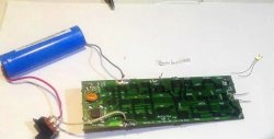
Manufacturing of BMS boards
If you plan to use 3 batteries in one circuit, then all controllers for each battery can be assembled on one board.
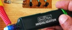
We make the board and prepare all the elements.

We install all the parts and solder them. We bite off the conclusion.


BMS board setup
Before connecting batteries to the circuit, each controller must be adjusted.
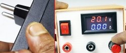
We set the voltage on the power supply to 4.2 V and connect to the first controller.

By rotating the variable resistor we achieve the initial glow LEDs.

Next, we configure the next two controllers in a similar way.
We solder the wires to the board and connect them to each battery.

Charging circuit
These controllers monitor excess voltage, but to regulate the charging current, you need to assemble a small circuit of two stabilizers that control current and voltage.

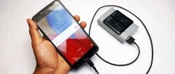
We will charge a line of three batteries from a 19 V laptop power supply. The first stabilizer on LM317 limits the voltage to 14 V, the second limits the current to 600 mA.
In principle, one LM317 microcircuit could be used for all tasks, but in this example the power would not be enough, so it was divided into two microcircuits.
We connect the circuit and charge the battery.
Glow everyone LEDs indicates charging is complete and all cells are fully charged.
This simple circuit will help you quickly and immediately charge many lithium-ion batteries.