Adding a relay block to the car: DRL, recorder, pneumatic signal
Modern cars are equipped with various electronic devices as standard. But what if your car was produced a long time ago, when many accessories were not yet known? You can modify the electrical circuit yourself, the main thing is to follow electrical safety measures.
Note: Our material relates to purely technical topics. Questions about the legality of making changes to the design are the topic of another article.
So, let's look at a typical set of electronic add-ons with tuning elements:
If you are familiar with the electrical part of a car, you probably know that any consumer (headlights, starter, fans, power windows) is turned on using a relay. This is convenient from a management point of view, and allows you to separate thin signal wires from thick power cables. To connect newly installed devices, we assemble a new relay block.
The operating algorithm is as follows: when starting the engine, the daytime running lights should light up and the recorder should turn on. After turning off the engine, these devices turn off. In addition, the DRLs must go out when the side lights or headlights are turned on: this is required by technical regulations.
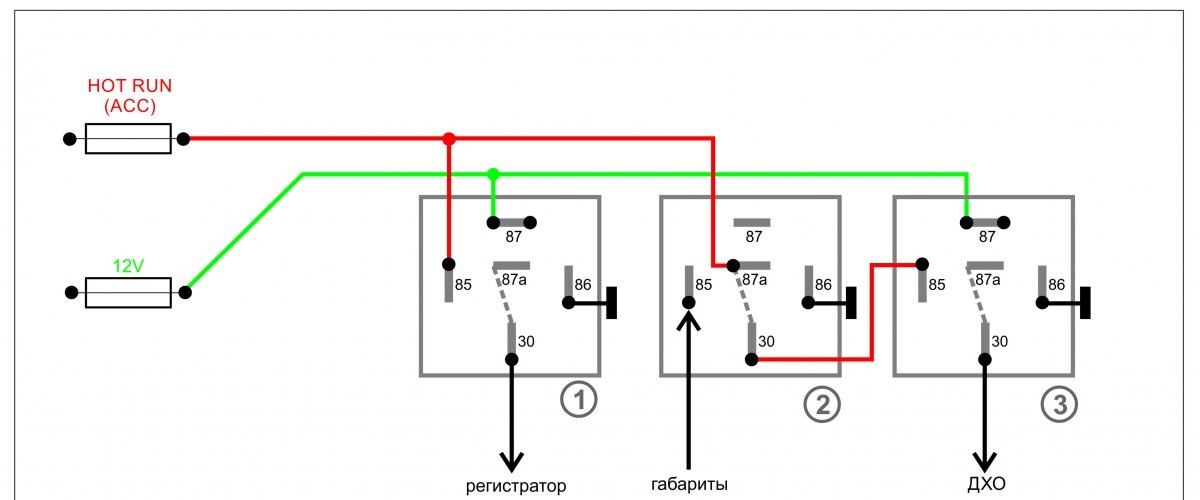
For implementation, you will need three standard 5-pin automotive relays (sold in a car store). In the diagram they are indicated by numbers 1, 2 and 3.
1. Green wire – power supply. 12 volts through a fuse are constantly supplied to contacts No. 87 (normally open) of relays 1 and 3. Output contacts No. 30 are connected to the positive inputs of the recorder and the running light module. The negative wire (ground) can be connected to the car body at the location where the devices are installed.
2. The red wire in the diagram supplies the control voltage of 12 volts, which appears after the engine starts (or turns the ignition key). In automotive circuits it is designated as “HOT RUN”. There are quite a lot of connection points: from the radio to the power supply to the fuel pump. The signal is easy to find in the description of your car.
3. When 12 volts appears on the red wire (contact No. 85), relay coils 1 and 3 are activated, the supply voltage through the green wire is turned on by the recorder and DRL (contacts No. 87 and No. 30 are closed).
4. On relay 3, the control voltage is supplied through normally closed contacts No. 87a and No. 30 of relay 2. When voltage is applied to contact No. 85 of relay 2, the coil is activated and stops the supply of control voltage to relay 3. The control signal comes from the side lights being turned on: The DRL goes out, but the recorder (via relay 1) continues to work.
The circuit can be upgraded by adding manual control.This will require three-way switches with three pairs of contacts.

With this connection method, you can control the relay block manually. In the “OFF” mode (middle position of the switch), the circuit is disabled. The “AVTO” mode starts the recorder and DRLs when the engine starts. In the “ON” position, you can turn on the equipment with the engine turned off:
1. To implement the project, on aliexpress A box for 6 relays and 6 fuses was purchased, complete with contact groups.
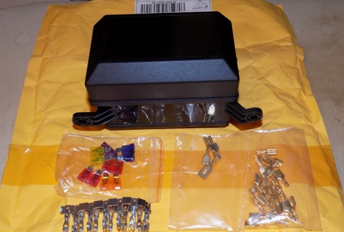
2. Switches, pneumatic signal button, crimp contacts, automotive relays.

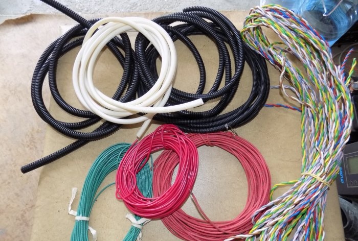
3. Wires, cambrics, automotive corrugation.
4. Side cutters, pliers, insulation stripping kit (ISR), soldering iron, electrical tape, heat-crimping casing.
Before starting work, it is advisable to print out a detailed wiring diagram linked to your car: with color-coded wires and power connection points. It is necessary to mark the contacts, otherwise errors during assembly may occur. The diagram adds relay No. 4 with a button to turn on the pneumatic signal and a front parking sensor switch.
Important! External connections may vary depending on the vehicle brand.
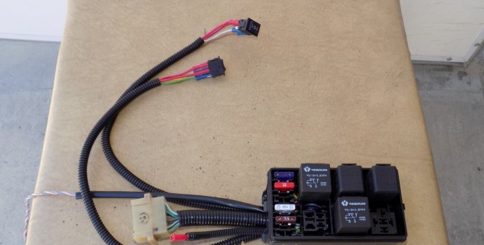
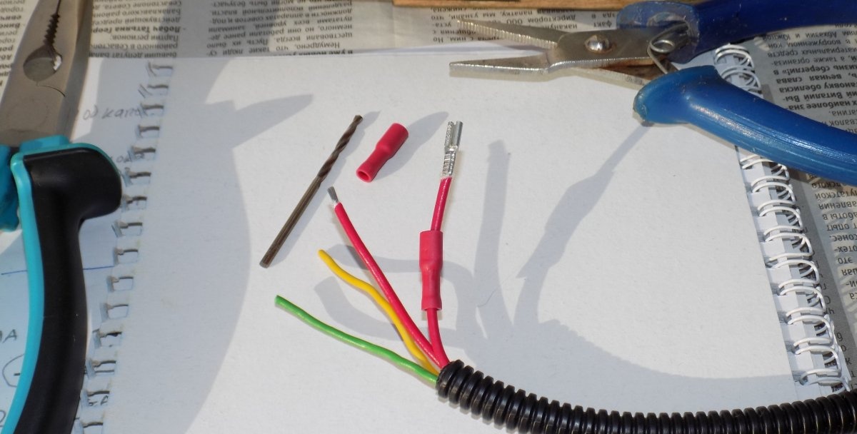
1. We carry out the wiring of wires and connectors for the relay according to the diagram.

2. Wires will inevitably cross each other; if the insulation is good, this is not a problem.
3. Contacts are crimped mechanically; a soldering iron is not used.

4. After connecting all the wires, we form bundles and place them in the corrugation.
5. To connect control and power wires, it is convenient to use a ready-made connector: in this case, from the steering column switch of a classic VAZ.
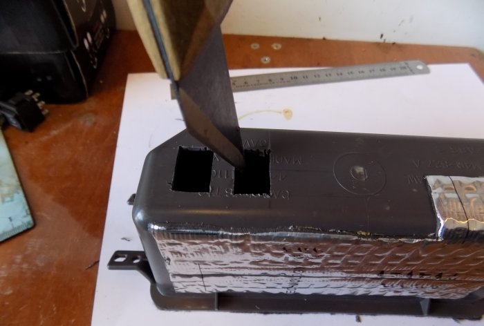
6. If the relay unit is installed under the hood, it must be covered with a standard cover. This is not necessary for salon installation.
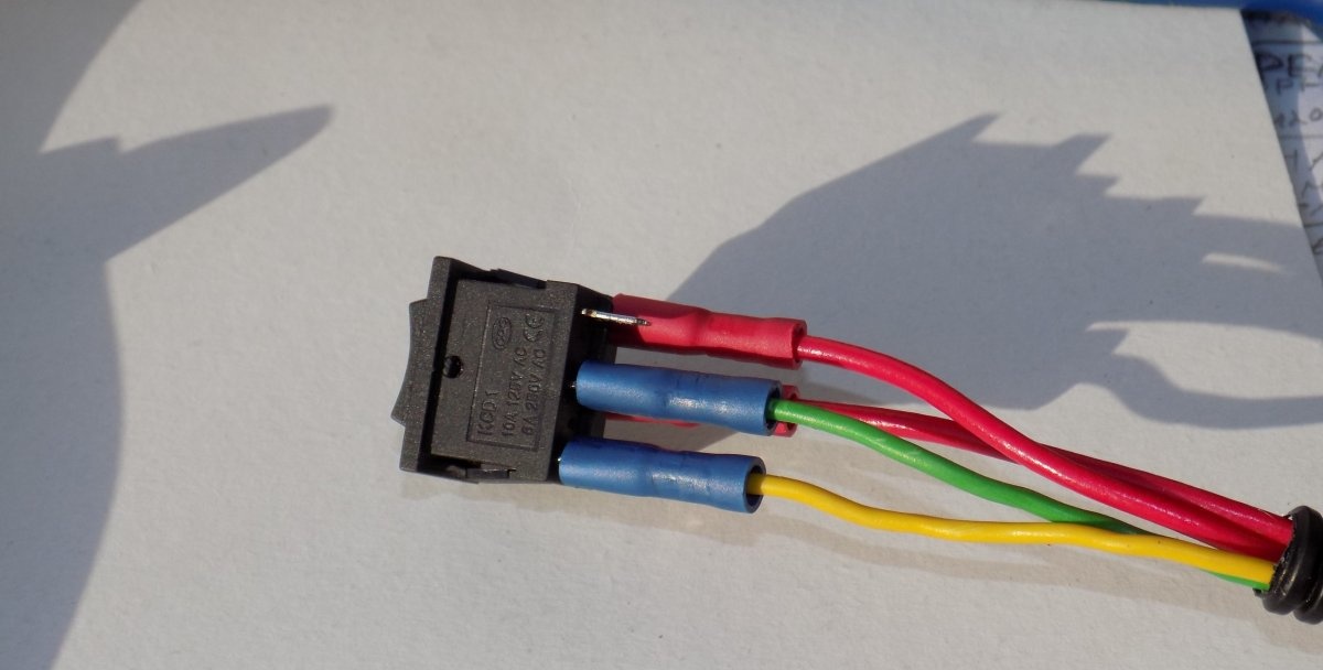
7. Connect the switches using crimp connectors.


8. We assemble a test circuit to check the correct installation (of course, outside the car and with an input fuse). We simulate all modes.

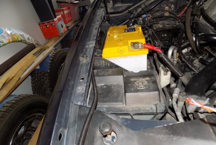
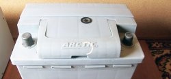
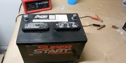
Power can be taken directly from the battery terminal, through a fuse. Or find the switching point in the standard fuse box (a diagram of your car is required).
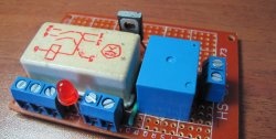
Important! In this box with aliexpress There are input fuses for each line.
All additional wiring is done in corrugation and secured to the body with ties.
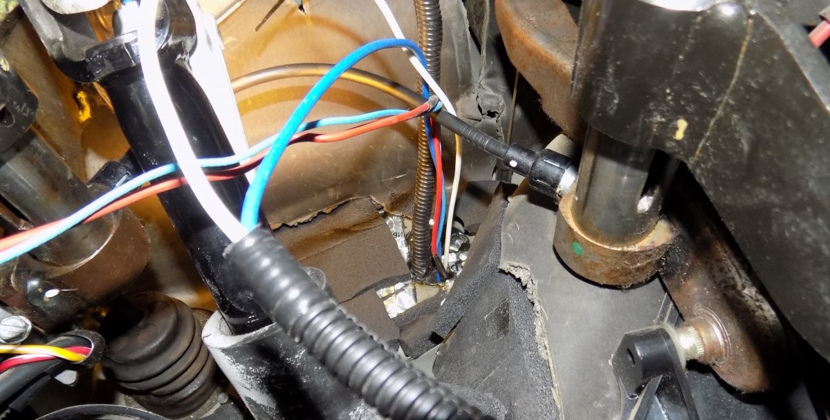
The harness is inserted into the passenger compartment through standard holes in the engine shield.


Inside the cabin, the cable is also laid in corrugation and attached to the structural elements.

All connections are made by soldering, insulated with thermocable and again corrugated.

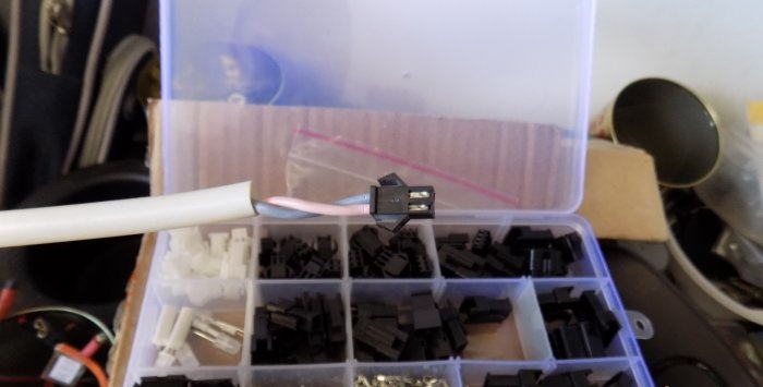
For quick connection, you can use quick-release connectors (from the same aliexpress).

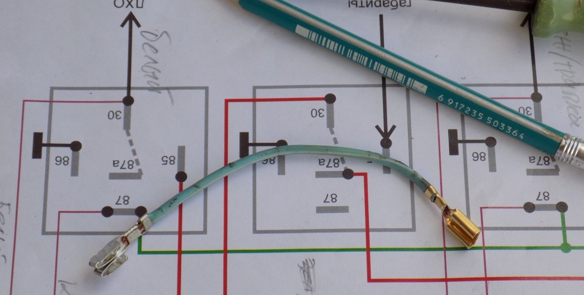
The signal from the dimensions does not have to be taken near the headlights. It is enough to make a tap (using soldering) from the connector of the light control unit.

We install switches (buttons) in the cabin. We select panel elements without disturbing the design.

Switches should be accessible and unnoticeable: for example, in niches for small items.

All wires are connected using removable contacts: for ease of dismantling when disassembling the interior.


As a result, control and power wires with contact connectors are concentrated at the location where the relay unit is installed.
We carry out a test switch on according to the diagram, check the functionality.

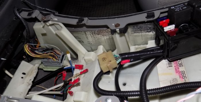
In this case, the relay unit is installed in the floor console between the driver and passenger. The installation location is individual for different vehicles. Brackets can be made for fixation.

Check the fuses in the block.

We finally fix the module in the console.

We disconnect the long wires from the switches, install the switches in the niche, and put them back together.

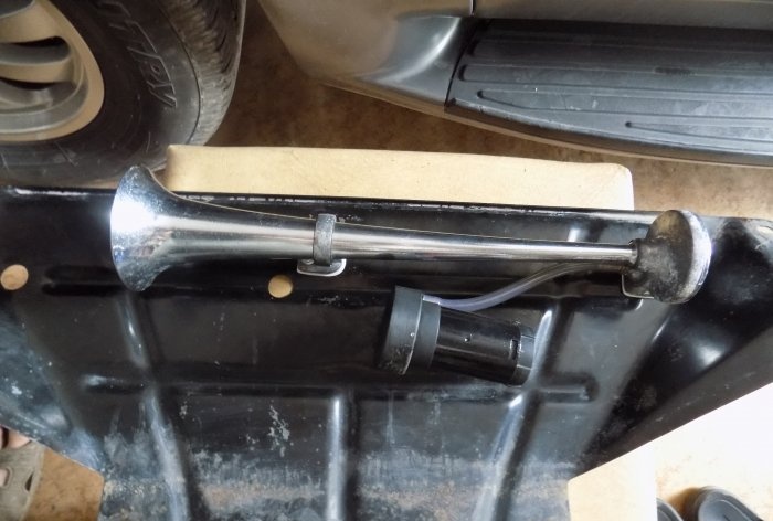
It is turned on separately from the standard horn, by a button on the control panel. To start a powerful compressor, a relay is installed (in the diagram: No. 4). The signal itself is attached to a frame element or underbody protection.
The wiring is neatly laid out in the engine compartment.

The corrugation is lowered to the installation site, the supply wire is connected to the pneumatic compressor.


Why through a relay? A direct connection will melt the signal button after 10 presses: the pneumatic compressor current is about 15 amperes.
Important: Direct power connection (using the car's standard fuses) is not recommended. In the event of a short circuit, you can cut off power to important components of the electrical circuit.
Any additional device is connected through its own fuse.
Note: Our material relates to purely technical topics. Questions about the legality of making changes to the design are the topic of another article.
So, let's look at a typical set of electronic add-ons with tuning elements:
- automatic daytime running lights;
- video recorder that turns on with the engine;
- pneumatic signal powered by an electric compressor.
If you are familiar with the electrical part of a car, you probably know that any consumer (headlights, starter, fans, power windows) is turned on using a relay. This is convenient from a management point of view, and allows you to separate thin signal wires from thick power cables. To connect newly installed devices, we assemble a new relay block.

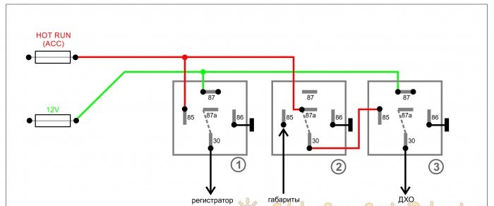
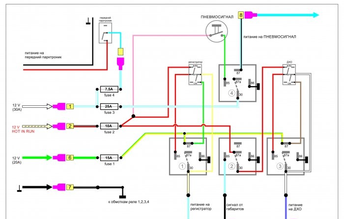
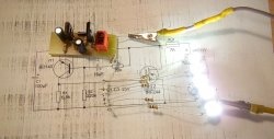
First, let's look at the diagram
The operating algorithm is as follows: when starting the engine, the daytime running lights should light up and the recorder should turn on. After turning off the engine, these devices turn off. In addition, the DRLs must go out when the side lights or headlights are turned on: this is required by technical regulations.
For implementation, you will need three standard 5-pin automotive relays (sold in a car store). In the diagram they are indicated by numbers 1, 2 and 3.
1. Green wire – power supply. 12 volts through a fuse are constantly supplied to contacts No. 87 (normally open) of relays 1 and 3. Output contacts No. 30 are connected to the positive inputs of the recorder and the running light module. The negative wire (ground) can be connected to the car body at the location where the devices are installed.
2. The red wire in the diagram supplies the control voltage of 12 volts, which appears after the engine starts (or turns the ignition key). In automotive circuits it is designated as “HOT RUN”. There are quite a lot of connection points: from the radio to the power supply to the fuel pump. The signal is easy to find in the description of your car.
3. When 12 volts appears on the red wire (contact No. 85), relay coils 1 and 3 are activated, the supply voltage through the green wire is turned on by the recorder and DRL (contacts No. 87 and No. 30 are closed).
4. On relay 3, the control voltage is supplied through normally closed contacts No. 87a and No. 30 of relay 2. When voltage is applied to contact No. 85 of relay 2, the coil is activated and stops the supply of control voltage to relay 3. The control signal comes from the side lights being turned on: The DRL goes out, but the recorder (via relay 1) continues to work.
The circuit can be upgraded by adding manual control.This will require three-way switches with three pairs of contacts.
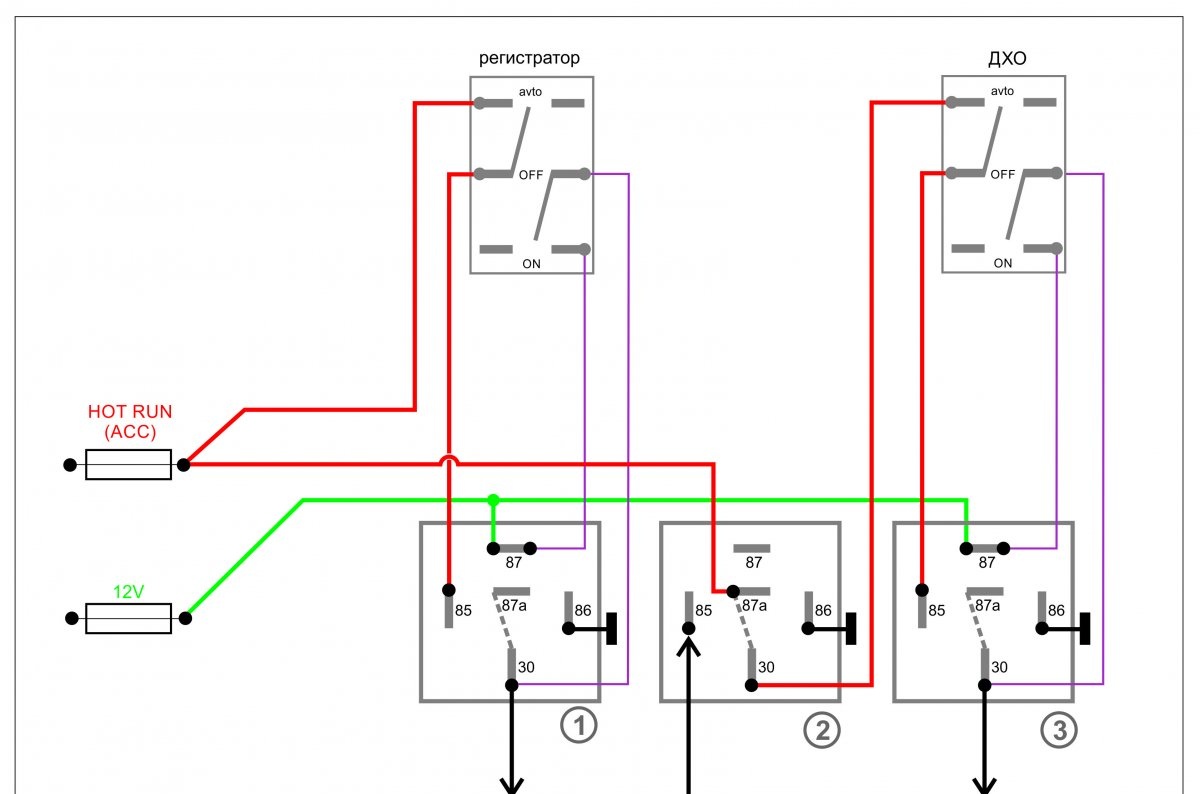
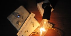
With this connection method, you can control the relay block manually. In the “OFF” mode (middle position of the switch), the circuit is disabled. The “AVTO” mode starts the recorder and DRLs when the engine starts. In the “ON” position, you can turn on the equipment with the engine turned off:
- for example, a recorder for monitoring a car in a supermarket parking lot;
- or illuminate the garage door with running lights without turning on the headlights.
Tools and materials
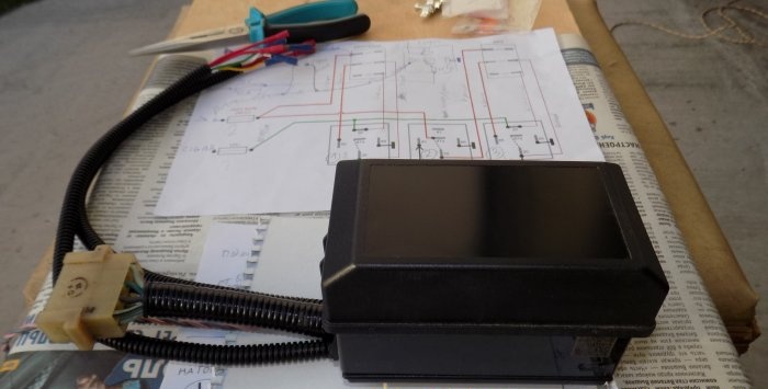
1. To implement the project, on aliexpress A box for 6 relays and 6 fuses was purchased, complete with contact groups.

2. Switches, pneumatic signal button, crimp contacts, automotive relays.

3. Wires, cambrics, automotive corrugation.

4. Side cutters, pliers, insulation stripping kit (ISR), soldering iron, electrical tape, heat-crimping casing.
Step-by-step installation process
Before starting work, it is advisable to print out a detailed wiring diagram linked to your car: with color-coded wires and power connection points. It is necessary to mark the contacts, otherwise errors during assembly may occur. The diagram adds relay No. 4 with a button to turn on the pneumatic signal and a front parking sensor switch.

Important! External connections may vary depending on the vehicle brand.
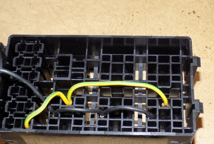
1. We carry out the wiring of wires and connectors for the relay according to the diagram.

2. Wires will inevitably cross each other; if the insulation is good, this is not a problem.

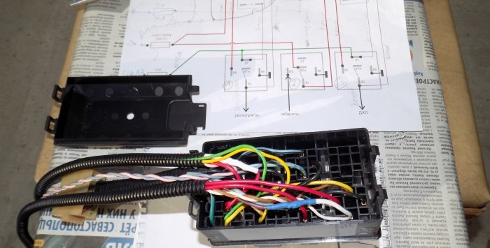
3. Contacts are crimped mechanically; a soldering iron is not used.
4. After connecting all the wires, we form bundles and place them in the corrugation.

5. To connect control and power wires, it is convenient to use a ready-made connector: in this case, from the steering column switch of a classic VAZ.

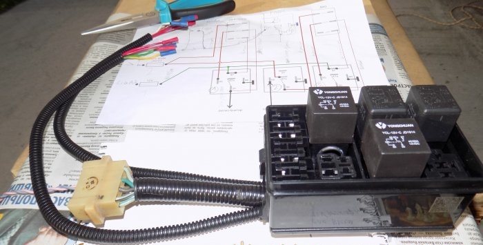
6. If the relay unit is installed under the hood, it must be covered with a standard cover. This is not necessary for salon installation.

7. Connect the switches using crimp connectors.
8. We assemble a test circuit to check the correct installation (of course, outside the car and with an input fuse). We simulate all modes.

Installation of wires inside the car
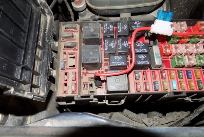
Power can be taken directly from the battery terminal, through a fuse. Or find the switching point in the standard fuse box (a diagram of your car is required).

Important! In this box with aliexpress There are input fuses for each line.
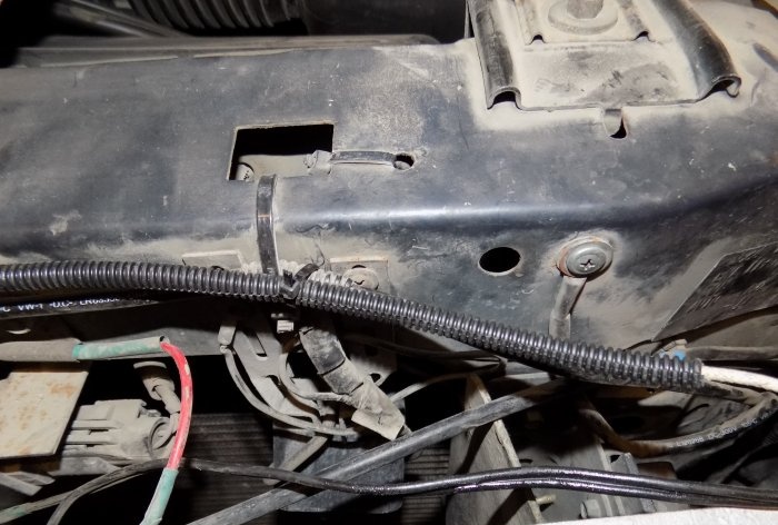
All additional wiring is done in corrugation and secured to the body with ties.

The harness is inserted into the passenger compartment through standard holes in the engine shield.


Inside the cabin, the cable is also laid in corrugation and attached to the structural elements.
All connections are made by soldering, insulated with thermocable and again corrugated.


For quick connection, you can use quick-release connectors (from the same aliexpress).


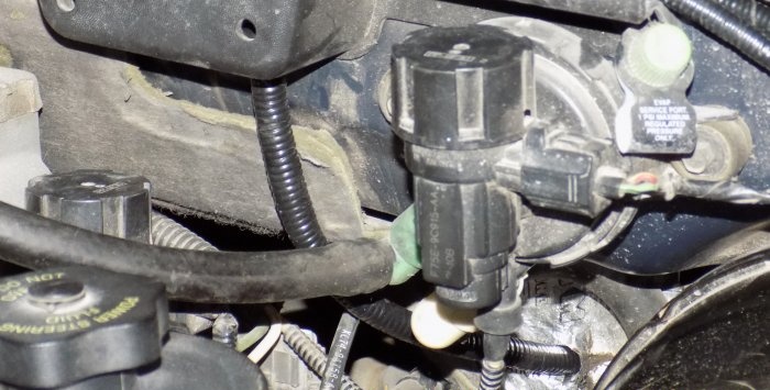
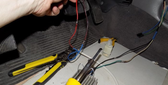
The signal from the dimensions does not have to be taken near the headlights. It is enough to make a tap (using soldering) from the connector of the light control unit.

We install switches (buttons) in the cabin. We select panel elements without disturbing the design.
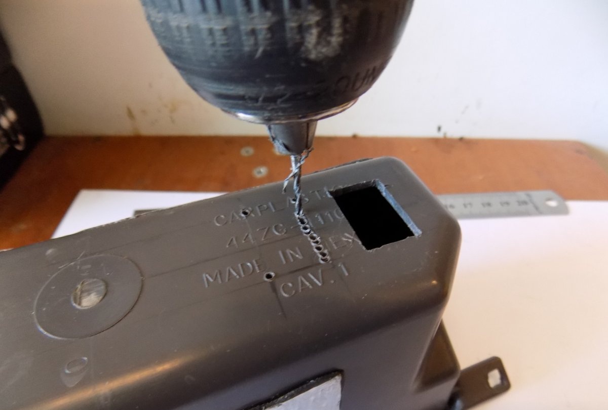

Switches should be accessible and unnoticeable: for example, in niches for small items.

All wires are connected using removable contacts: for ease of dismantling when disassembling the interior.


As a result, control and power wires with contact connectors are concentrated at the location where the relay unit is installed.

We carry out a test switch on according to the diagram, check the functionality.

In this case, the relay unit is installed in the floor console between the driver and passenger. The installation location is individual for different vehicles. Brackets can be made for fixation.

Check the fuses in the block.

We finally fix the module in the console.

We disconnect the long wires from the switches, install the switches in the niche, and put them back together.

Pneumatic signal connection
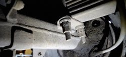
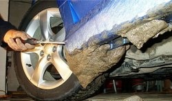
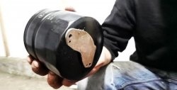
It is turned on separately from the standard horn, by a button on the control panel. To start a powerful compressor, a relay is installed (in the diagram: No. 4). The signal itself is attached to a frame element or underbody protection.

The wiring is neatly laid out in the engine compartment.


The corrugation is lowered to the installation site, the supply wire is connected to the pneumatic compressor.


Why through a relay? A direct connection will melt the signal button after 10 presses: the pneumatic compressor current is about 15 amperes.
Important: Direct power connection (using the car's standard fuses) is not recommended. In the event of a short circuit, you can cut off power to important components of the electrical circuit.
Any additional device is connected through its own fuse.
Similar master classes


Particularly interesting
Comments (2)
