How to check the armature of a power tool at home

Self-checking the motor armature can easily be done at home. This will allow, firstly, to independently restore the functionality of the instrument, and secondly, not to overpay a specialist for a fairly simple operation. To check you only need a screwdriver and multimeter. Additionally, you can purchase a special device for determining interturn short circuits.
Stage 1. Visual inspection of the tool
Very often there are situations when the tool still works, but no longer as it should. And in 30% of cases the culprit is a burnt anchor. This can be detected visually, even before opening the case.
Indirect signs of a “tired” electric motor armature are the following problems:
- When the electric motor is running, very strong sparking is visible on the commutator.
- When trying to start a grinder (drill, circular saw, etc.), a severe voltage drop is observed (the lighting blinks).
- Starting the electric motor is accompanied by sharp jerks.
- There is a characteristic smell of burnt wiring coming from the housing.
- The tool does not gain the same power.
Please note that more than half of these signs may also indicate simple wear of the motor brushes. If they are worn out or crumbled, then the anchor most likely has nothing to do with it. We replace them with new ones, clean the collector from graphite deposits, and calmly continue working. If the brushes look intact, and the above symptoms are observed, with an 80% probability we can say that the problem is in the motor armature.
If the power tool shows no signs of life at all, there may be many more reasons, and more than just checking the armature will be needed.
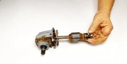
Stage 2. Disassembling the power tool
One way or another, if everything is in order with the brushes, you cannot do without disassembling the tool. At this stage, the most important thing is not to do more harm. Particular attention should be paid to the correct selection of a screwdriver, since it will be problematic to unscrew damaged screws, and the check will turn into painful plumbing work. Some tools use fasteners of different lengths. Their location needs to be remembered (it is better to write it down or sketch it).
In order to successfully assemble a power tool after diagnosis and repair, beginners are recommended to photograph each stage of disassembly. This will help a lot if you forget which part was there before checking.
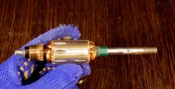
Stage 3. Preparing the motor armature for testing
After the anchor has been removed from the housing, it is advisable to prepare it for diagnostics. The procedure involves thoroughly cleaning the collector lamellas from graphite deposits. If this is not done, further testing may not give the required result.
You can remove the plaque using a rag and alcohol. If there is not plaque on the lamellas, but a thick layer of carbon deposits, it will have to be removed with fine-grained sandpaper. Please ensure that there are no visible abrasive grooves left on the commutator. This will worsen the contact of the lamellas with the brushes and also accelerate their wear.


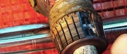
Stage 4. Visual inspection of the anchor before checking
You need to look at the following:
- Collector lamellas. They should not show much wear.
- Armature winding of an electric motor. We are looking for breaks or visible traces of burning wires.
- Contacts. The entire winding is soldered to the collector lamellas. These points need to be checked for integrity.
If the excavation on the collector is too deep, the anchor must be replaced. Burn marks on the windings or contacts indicate that the part is faulty. You can rewind, of course, but this is a thankless task and requires special skills. It's easier to buy a new one.
Stage 5. Checking the armature with a multimeter
Checking the motor armature with a multimeter consists of two stages. First of all, you need to ring it for a breakdown. For this multimeter is set to circuit test mode with an audible signal.

Next, we pass one probe along the collector lamellas, and the second along the armature body.

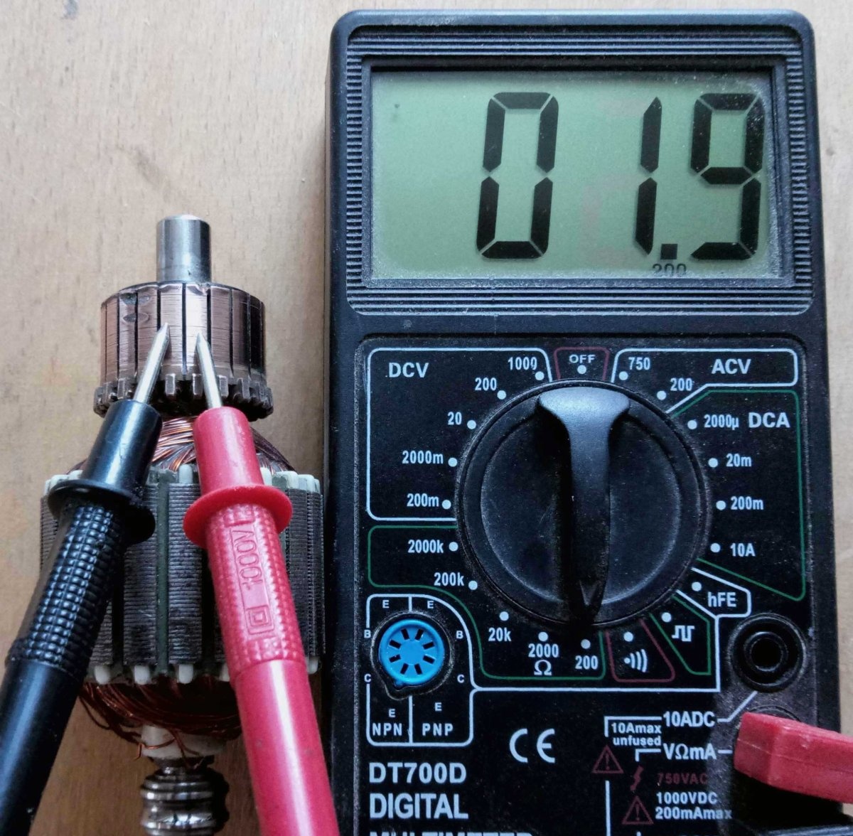
The second stage of checking the armature with a multimeter is to measure the resistance between adjacent windings. To do this, the device is set to resistance detection mode at the very minimum threshold (usually 200 Ohms).
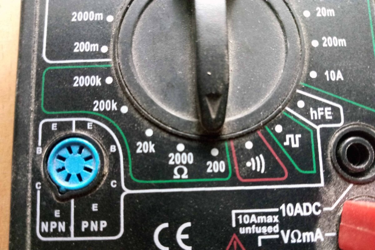
Next, the probes are applied to the adjacent lamellas of the collector, and the readings are recorded on the screen. When measuring the resistance between all adjacent lamellas, the value should be the same. If this is not the case, the anchor is faulty.
The same thing is indicated by the complete absence of resistance on any of the windings.
Stage 6. Checking the armature for interturn short circuit
Before checking the motor armature for an interturn short circuit, you need to acquire a special device. It costs pennies, and there is a lot of information about it on the Internet.
The essence of checking the anchor is to apply this same device to all sections of the hull. The LED indicator indicates a malfunction.
Stage 7. Replacing the armature and reassembling the tool
The faulty anchor is either sent for rewinding or replaced with a new one. Fortunately, today you can find suitable components in online stores even for the cheapest Chinese instrument. Before installation, it is advisable to check a new or restored anchor using the algorithm described above.
If everything is normal, we put everything back together and work. When changing the motor armature, it is also recommended to install new brushes. Fortunately, they are cheap.