How to make a band saw from bicycle wheels
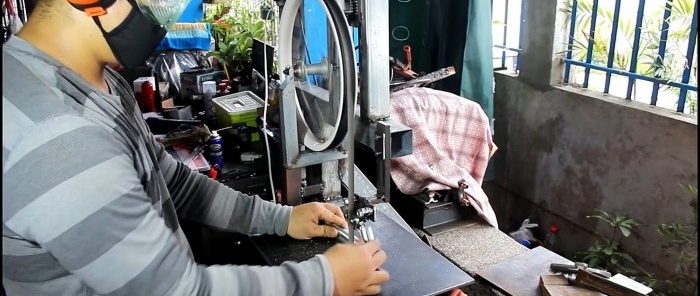
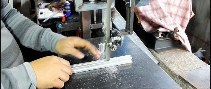
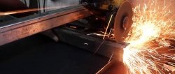
To cut metal workpieces, you can make a band saw. Bicycle rims are perfect for use as pulleys. When using a sufficiently powerful motor, a homemade saw is generally in no way inferior to a purchased one.
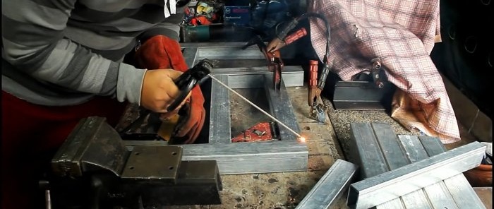
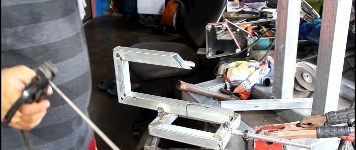
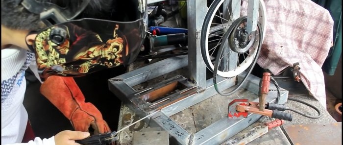
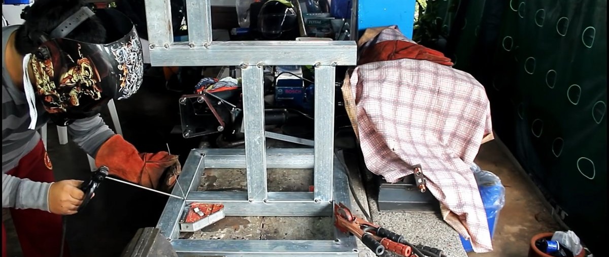
A rectangular frame of the machine sole is welded from a profile pipe. A frame from the same pipe is welded into it at a right angle. All sizes are selected individually, based on the length of the selected tape. The frame is welded to the crossbar inside the sole. Its racks must be shifted as in the photo. The motor will be installed in the lower offset, and the table in the upper offset.

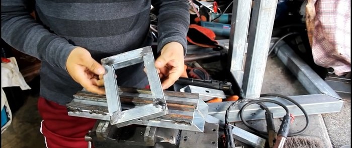
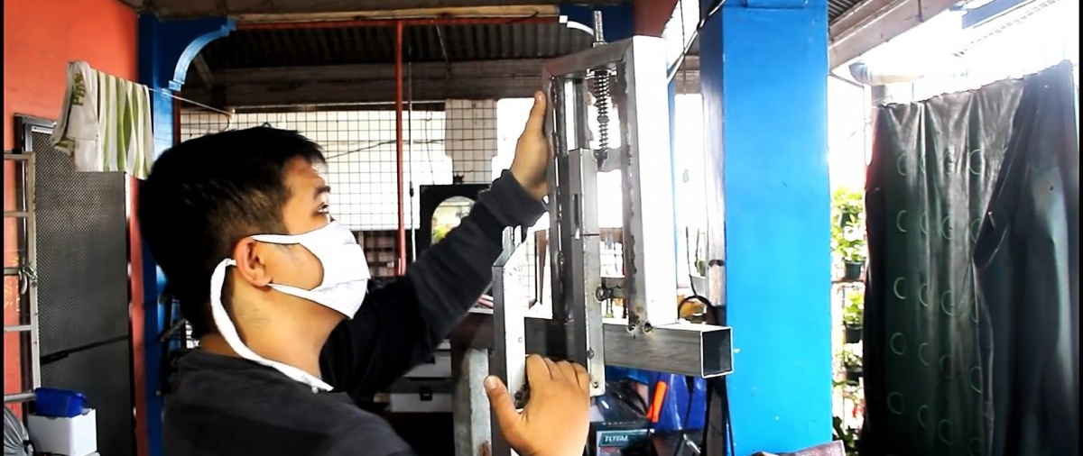
Next you need to make a guide for attaching the upper belt drive pulley. It consists of a frame with a narrow profile and two sections of a large pipe.A square is welded to them to form runners for sliding the frame. Tubes with runners are welded on top of the frame so that a frame is inserted between them.

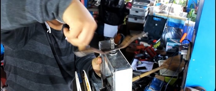
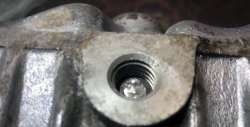
A hole is made in the frame itself, and an M12 pin is welded into it. Then a fork is welded to it to install a bicycle rim.
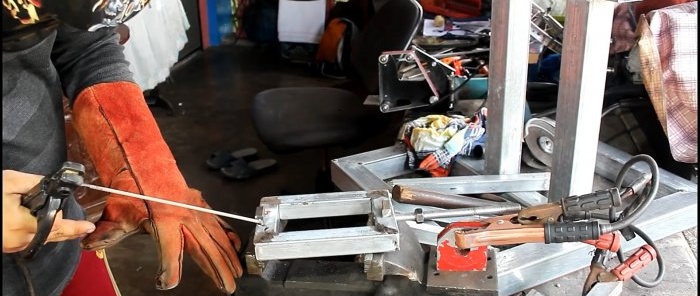
Springs and a small piece of profile pipe with a hole are put on the stud, then a nut is screwed on. The frame is inserted into the runners, and the tube on the stud is welded to the guides. Handles can be welded to the nut on the stud so that you can rotate it without a key when adjusting the tension of the blade.


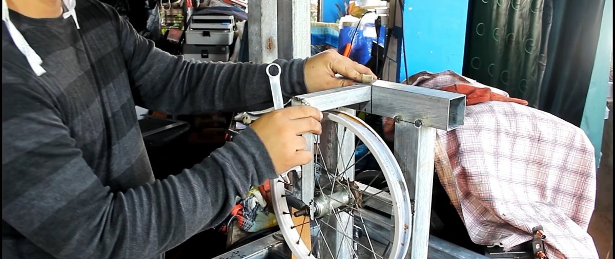
A disc is inserted into the fork, a cloth is thrown over it and a measurement is taken to determine the height of the lower pulley. Following the mark, a piece of pipe with a hole for the disk axis is welded to the frame. Next, an L-shaped blank is welded to increase the rigidity of the lower belt drive pulley.

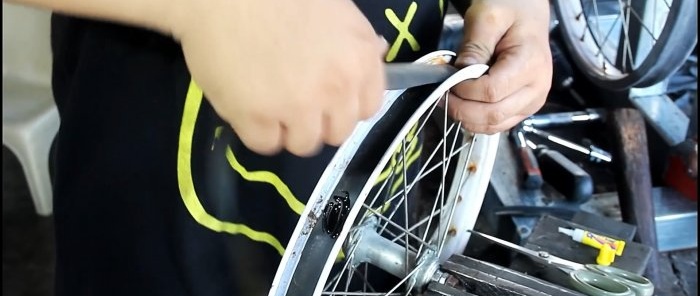
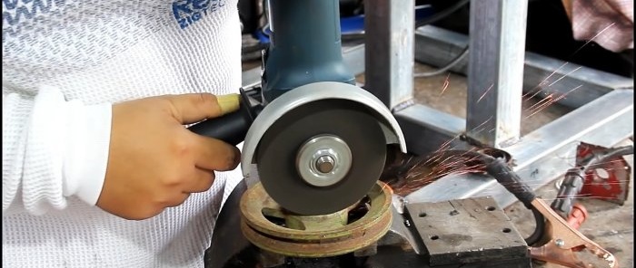
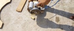
The discs are removed, and rubber strips cut from the chamber are glued onto them in several layers. On the tubercles from the spokes, the rubber is drilled out with a small crown, and another strip is glued on top. Then, rings cut from their original chamber are pulled over the disks.
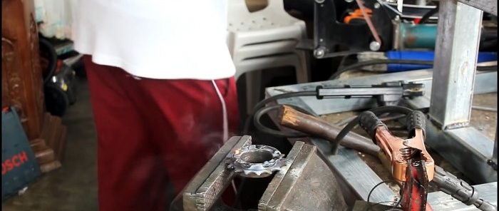
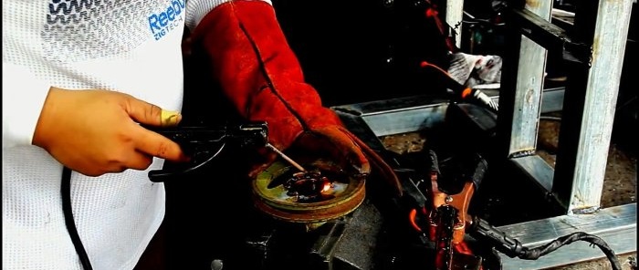
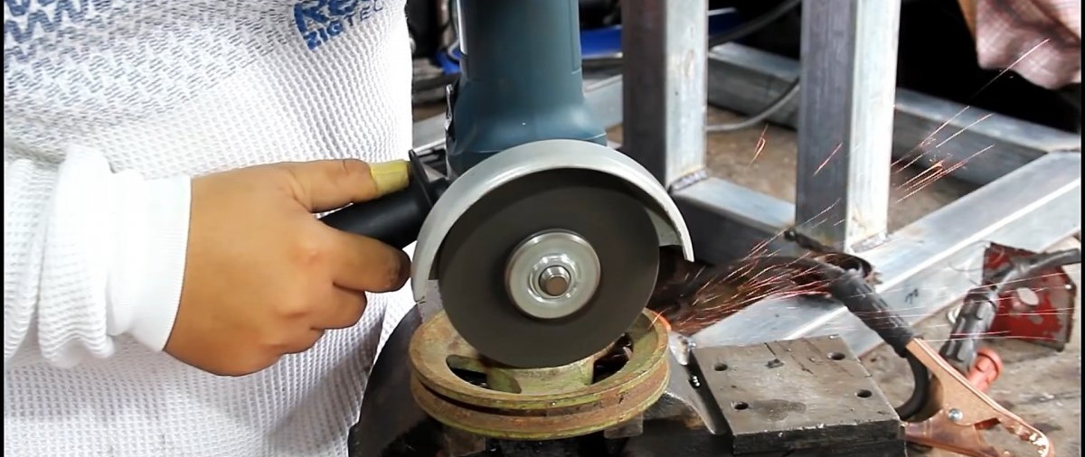
A pulley under the belt is welded to the axis of the lower disk to the sprocket. After this, the discs are installed in place, and the saw blade is tensioned on them.
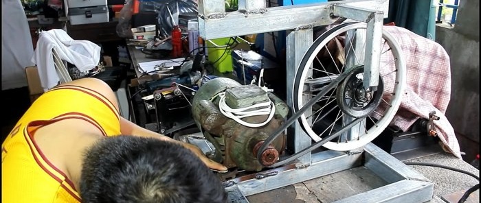
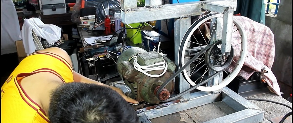
The base is welded to the machine bed, and the motor is screwed onto it. Then a belt is pulled between it and the pulley on the disk.
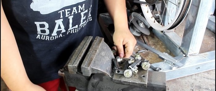
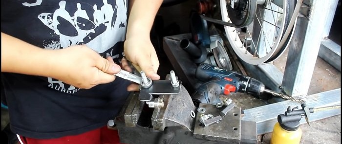
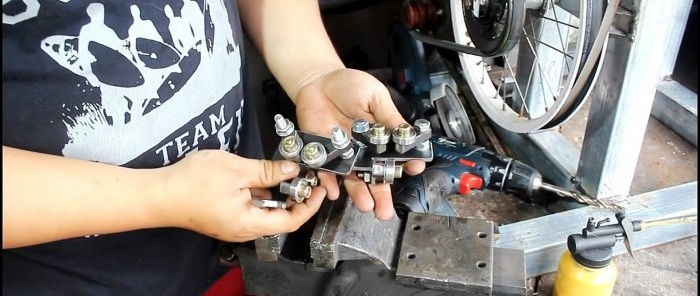
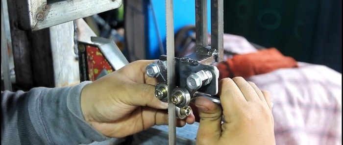
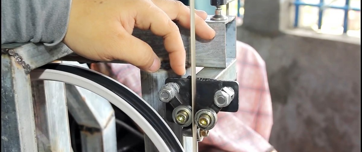
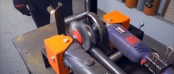
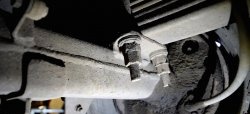
To prevent the saw blade from moving away when sawing, it is necessary to make limit rollers at the top and bottom. Bearings can be used as these. For this purpose, an L-shaped bracket is made from sheet steel. It is equipped with 3 bearings on square arms.Of these, 2 will slide towards each other to hold the canvas on the sides, and one is attached relative to them at a right angle to support it from the edge.
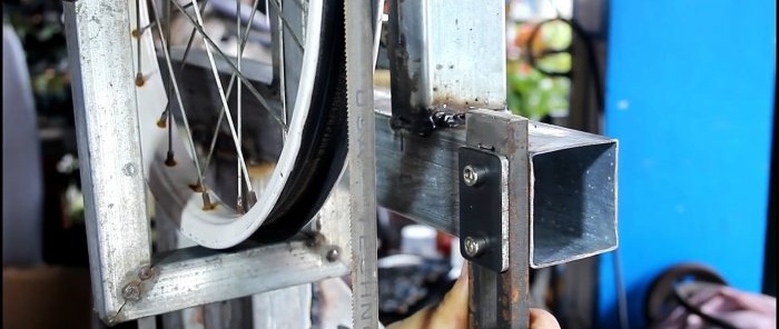
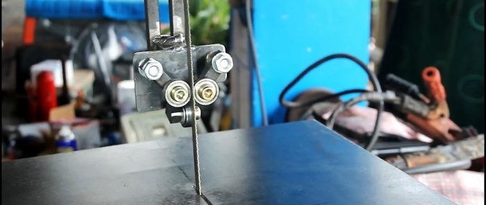
One bracket with bearings is welded to the frame at the bottom immediately in front of the pulley through a pipe spacer. For the second, you need to make a sliding guide to change the position of the rollers in case of installing a longer or shorter blade.

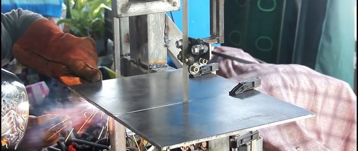
The final stage of assembly is installing the table. It is cut from 6 mm sheet steel. A slot is made on the table for the canvas. Then it is welded to the frame at the location where the posts are displaced.
The result is a very convenient, maintainable band saw. Only the bearings inside bicycle rims can break, which is easily repaired. The design provides for tension adjustment and quick replacement of the saw blade. To do this, you just need to fold the drive belt away from the motor.

Basic materials:
- profile pipes of different diameters;
- square 6-10 mm;
- M12 pin;
- rims from a children's bicycle - 2 pcs.;
- band saw blade;
- electric motor;
- pulleys for the belt – 2 pcs.;
- drive belt;
- small bearings – 6 pcs.;
- sheet steel 6 mm.
Band saw manufacturing process
A rectangular frame of the machine sole is welded from a profile pipe. A frame from the same pipe is welded into it at a right angle. All sizes are selected individually, based on the length of the selected tape. The frame is welded to the crossbar inside the sole. Its racks must be shifted as in the photo. The motor will be installed in the lower offset, and the table in the upper offset.

Next you need to make a guide for attaching the upper belt drive pulley. It consists of a frame with a narrow profile and two sections of a large pipe.A square is welded to them to form runners for sliding the frame. Tubes with runners are welded on top of the frame so that a frame is inserted between them.


A hole is made in the frame itself, and an M12 pin is welded into it. Then a fork is welded to it to install a bicycle rim.


Springs and a small piece of profile pipe with a hole are put on the stud, then a nut is screwed on. The frame is inserted into the runners, and the tube on the stud is welded to the guides. Handles can be welded to the nut on the stud so that you can rotate it without a key when adjusting the tension of the blade.


A disc is inserted into the fork, a cloth is thrown over it and a measurement is taken to determine the height of the lower pulley. Following the mark, a piece of pipe with a hole for the disk axis is welded to the frame. Next, an L-shaped blank is welded to increase the rigidity of the lower belt drive pulley.
The discs are removed, and rubber strips cut from the chamber are glued onto them in several layers. On the tubercles from the spokes, the rubber is drilled out with a small crown, and another strip is glued on top. Then, rings cut from their original chamber are pulled over the disks.

A pulley under the belt is welded to the axis of the lower disk to the sprocket. After this, the discs are installed in place, and the saw blade is tensioned on them.


The base is welded to the machine bed, and the motor is screwed onto it. Then a belt is pulled between it and the pulley on the disk.

To prevent the saw blade from moving away when sawing, it is necessary to make limit rollers at the top and bottom. Bearings can be used as these. For this purpose, an L-shaped bracket is made from sheet steel. It is equipped with 3 bearings on square arms.Of these, 2 will slide towards each other to hold the canvas on the sides, and one is attached relative to them at a right angle to support it from the edge.


One bracket with bearings is welded to the frame at the bottom immediately in front of the pulley through a pipe spacer. For the second, you need to make a sliding guide to change the position of the rollers in case of installing a longer or shorter blade.


The final stage of assembly is installing the table. It is cut from 6 mm sheet steel. A slot is made on the table for the canvas. Then it is welded to the frame at the location where the posts are displaced.


The result is a very convenient, maintainable band saw. Only the bearings inside bicycle rims can break, which is easily repaired. The design provides for tension adjustment and quick replacement of the saw blade. To do this, you just need to fold the drive belt away from the motor.

Watch the video
Similar master classes


Particularly interesting

Comments (0)
