Powerful linear voltage stabilizer
To power various electronic devices and DIY circuits, you need a power source whose output voltage can be adjusted within a wide range. With its help, you can observe how the circuit behaves at a particular supply voltage. At the same time, it must be able to produce high current to power a powerful load, and minimal ripple at the output. A linear voltage stabilizer - the LM338 microcircuit - is ideal for the role of such a power source; it provides a current of up to 5 A, has protection against overheating and short circuits at the output. Its connection diagram is quite simple, it is presented below.
Scheme

The LM338 chip has three pins - input (in), output (out) and control (adj). We apply a constant voltage of a certain value to the input, and remove a stabilized voltage from the output, the value of which is set by variable resistor P2. The output voltage is adjustable from 1.25 volts to the input value, with a deduction of 1.5 volts. Simply put, if the input is, for example, 24 volts, then the output voltage will vary from 1.25 to 22.5 volts.You should not apply more than 30 volts to the input; the microcircuit may go into protection. The larger the capacitance of the capacitors at the input, the better, because they smooth out the ripples. The capacitance of the capacitors at the output of the microcircuit must be small, otherwise they will retain a charge for a long time and the output voltage will be regulated incorrectly. In this case, each electrolytic capacitor must be shunted with a film or ceramic capacitor with a low capacity (in the diagram these are C2 and C4). When using a circuit with high currents, the microcircuit must be installed on a radiator, because it will dissipate the entire voltage drop. If the currents are small - up to 100 mA, a radiator is not required.

Stabilizer assembly
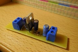
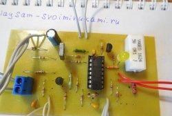
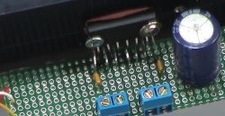
The entire circuit is assembled on a small printed circuit board measuring 35 x 20 mm, which can be manufactured using the LUT method. The printed circuit board is completely ready for printing; there is no need to mirror it. Below are some photos of the process.
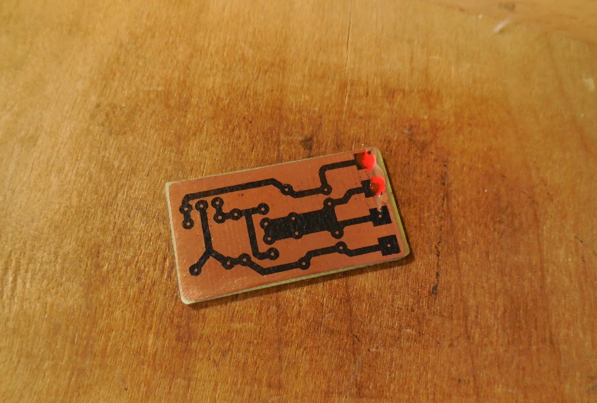


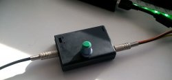
It is advisable to tin the tracks, this will reduce their resistance and protect them from oxidation. When the printed circuit board is ready, we begin to solder the parts. The microcircuit is soldered directly onto the board, with its back towards the edge. This arrangement allows you to mount the entire board with the microcircuit on the radiator. The variable resistor is output from the board on two wires. You can use any variable resistor with a linear characteristic. In this case, its middle pin is connected to any of the outer ones, the resulting two contacts go to the board, as can be seen in the photo. It is most convenient to use a terminal block to connect the input and output wires. After assembly, it is necessary to check the correct installation.


Launch and testing
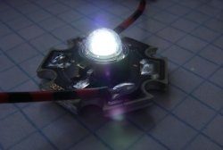
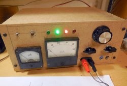
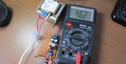
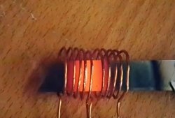
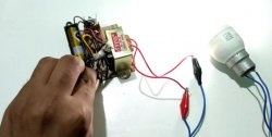
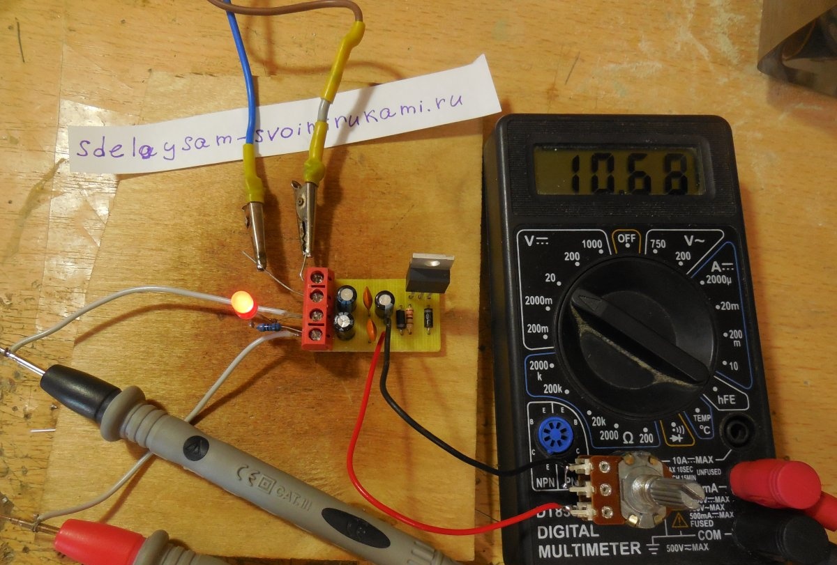
When the board is assembled, you can proceed to testing.We connect a low-power load to the output, for example, Light-emitting diode with resistor and voltmeter to monitor voltage. We apply voltage to the input and monitor the voltmeter readings; the voltage should change when the knob is rotated from minimum to maximum. Light-emitting diode this will change the brightness. If the voltage is regulated, then the circuit is assembled correctly, you can place the microcircuit on a radiator and test it with a more powerful load. This adjustable stabilizer is ideal for use as a laboratory power supply. Particular attention should be paid to the choice of microcircuit, because it is very often counterfeited. Fake microcircuits are cheap, but easily burn out at a current of 1 - 1.5 Amperes. The original ones are more expensive, but they honestly provide the declared current of up to 5 Amps. Happy assembly.
Watch the video
The video clearly shows the operation of the stabilizer. As the variable resistor rotates, the voltage changes smoothly from minimum to maximum and vice versa, Light-emitting diode At the same time, the brightness changes.