Diagram of a simple metal detector

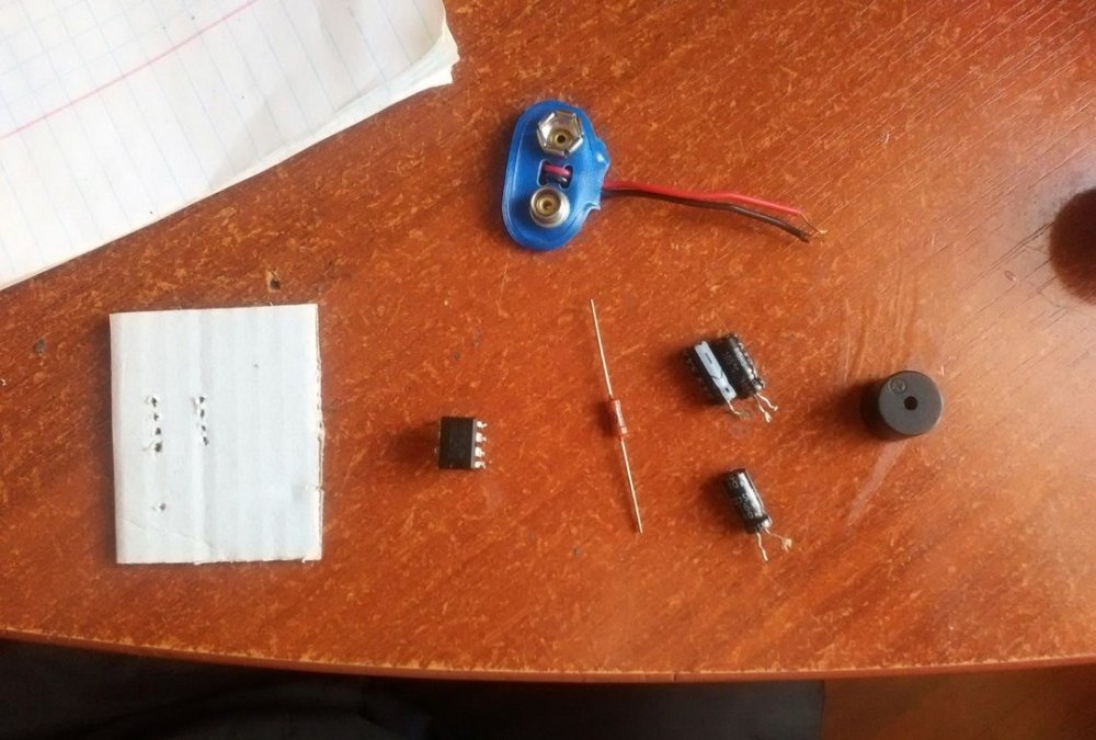
We will need
- Chip NE555P.
- Resistor 51 kOhm.
- Capacitor 2.2 uF (2 pieces).
- Capacitor 10 µF.
- Buzzer.
- Krona type battery and connector for it.
- Copper wire 0.2 mm.
- Cardboard 1-2 mm thick.
Making a simple metal detector
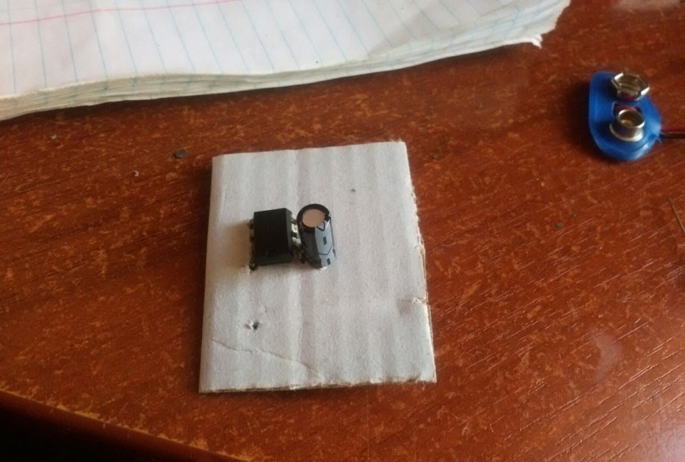
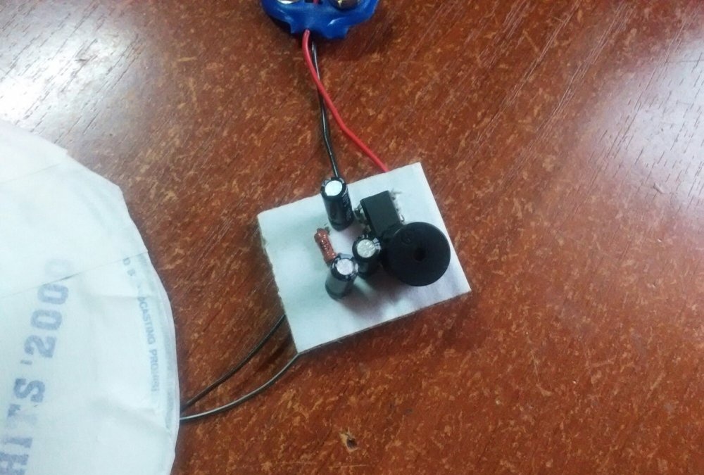
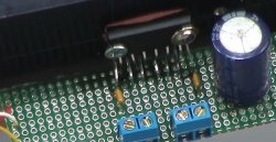
We will assemble the diagram on a piece of cardboard. In it, for each part, I made holes with a needle, since the legs of the radio components themselves are too thin. First, insert the microcircuit. Now we solder the negative leg of the 2.2 µF capacitor to the very first leg.
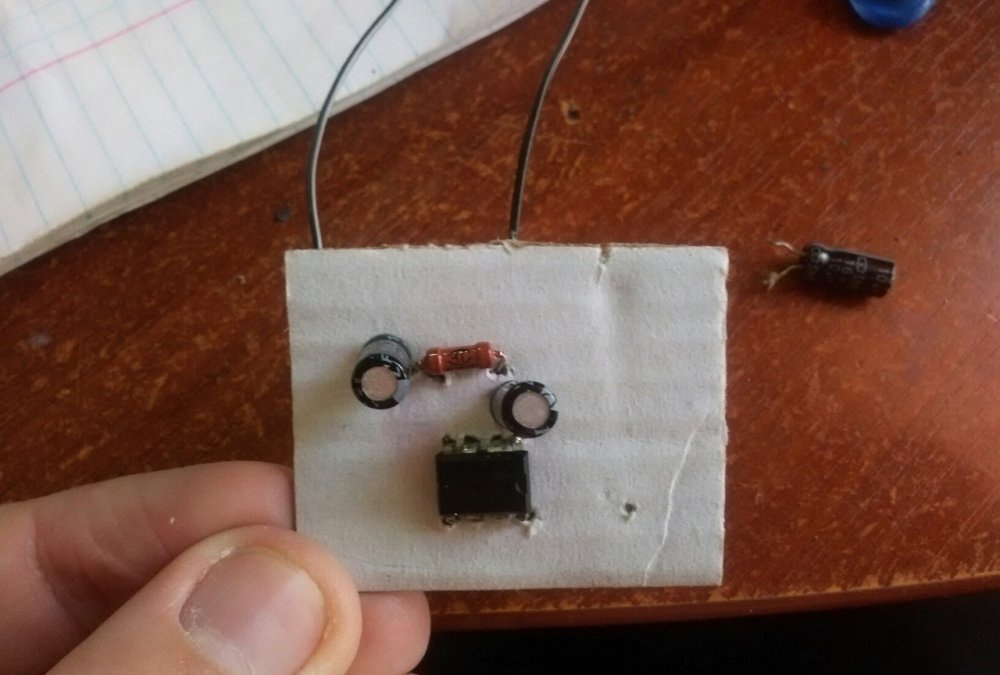
Now we insert the resistor. We solder one leg to the second leg of the microcircuit and the plus of the capacitor. We solder the second leg to the third leg of the microcircuit.

Now we insert a 2.2 µF capacitor.We also solder the negative leg to the third leg of the microcircuit. The positive one will go to the coil later, we will make it later. I soldered one wire to this leg. We also solder one wire to the second leg.

To the negative leg of the 2.2 µF capacitor we solder the positive leg of the 10 µF capacitor. The buzzer leg must be connected to the negative one. We connect the remaining buzzer leg to the first leg of the microcircuit. To connect the buzzer, I use blue and pink wires in the diagram.

Now all that remains is to short-circuit the second and sixth legs of the microcircuit. And also the fourth and eighth, to the eighth we solder the positive wire from the connector for the crown. We solder the negative wire from the connector to the first leg of the microcircuit.
The scheme itself is ready.

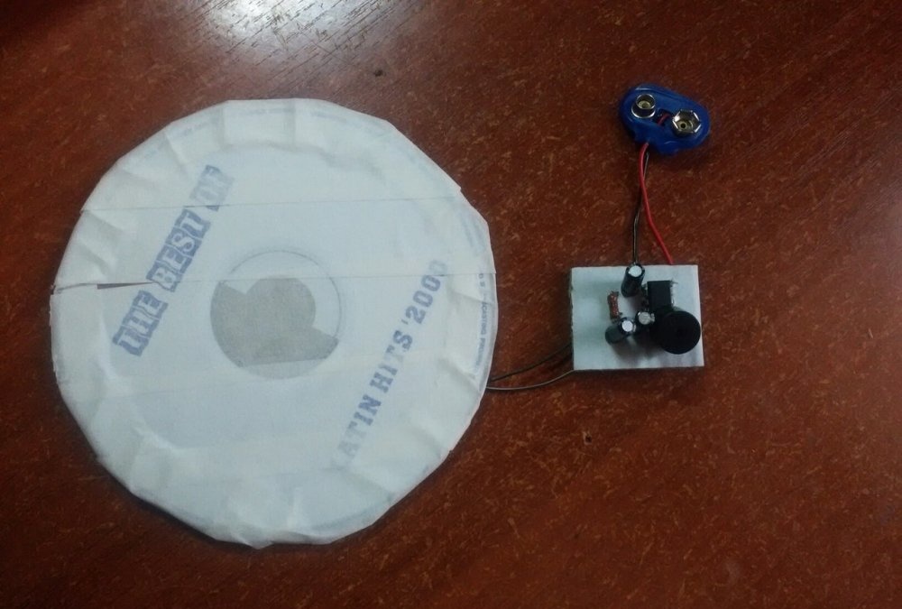
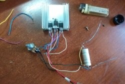
Now let's make a coil. It will require two CDs or DWD disks. Cut a circle with a diameter of 50 mm from cardboard.

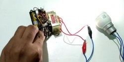
Now we glue this circle between the disks. At first I tried using superglue, but it didn't stick to anything. Therefore, the gluing areas on the disks had to be scraped to make the surface rough, and instead of superglue I used hot glue. Now we begin to wind the wire onto the cardboard. You need to wind 315 turns. After winding, solder the ends of the coil to the two wires that were brought out before (I have them black). This completes the production of the metal detector. All that's left to do is make a handle for it.
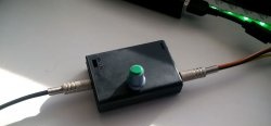
The board turned out to be very compact and, even together with the crown, will fit into almost any case. You can take a thick PVC pipe, cut one end at 45 degrees, and glue a coil to it. And place the diagram and crown in the pipe itself. As soon as you insert the battery, the buzzer will start beeping, and when the coil is above the metal, the buzzer will start beeping differently, I think you will immediately understand.
Similar master classes


Particularly interesting
Comments (10)
